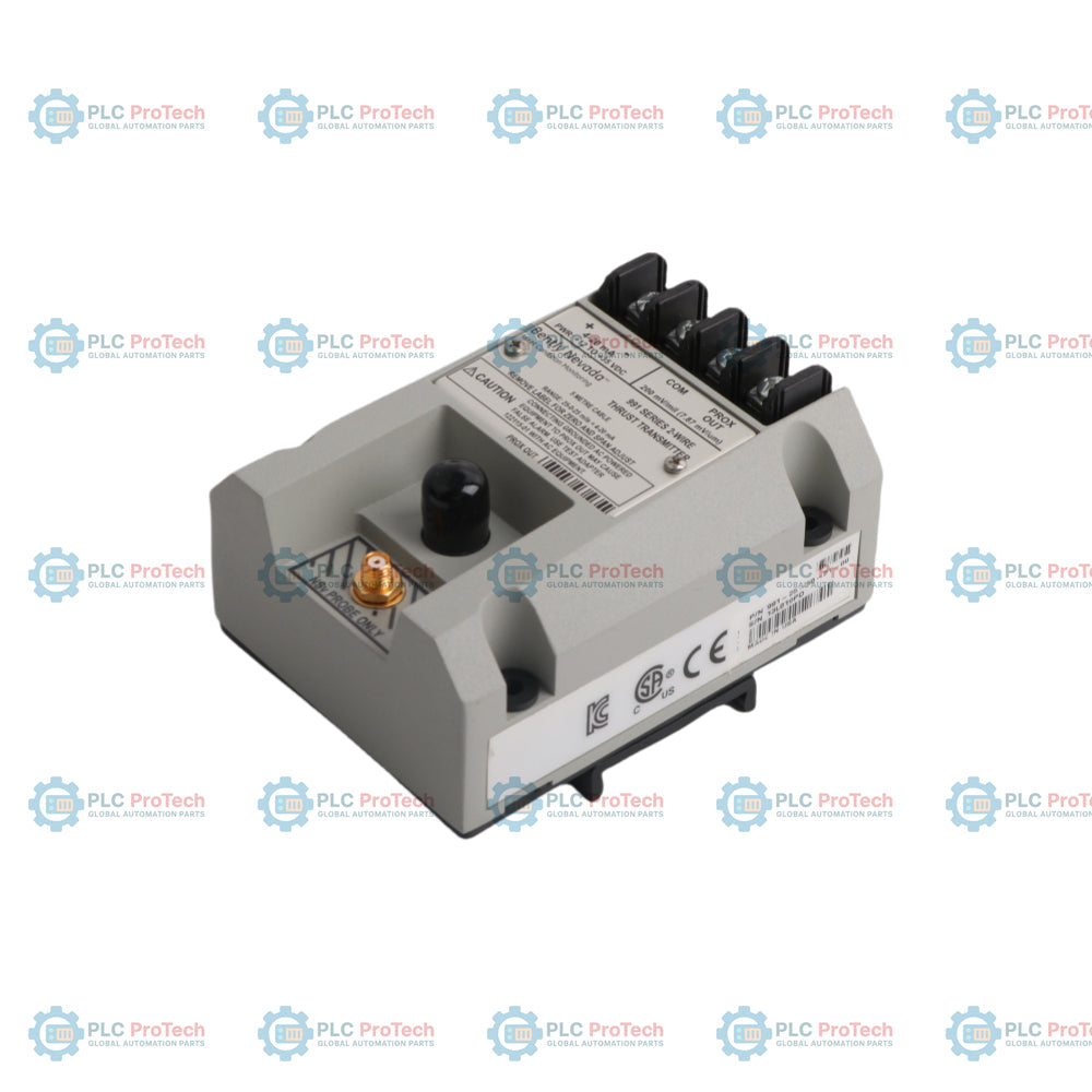
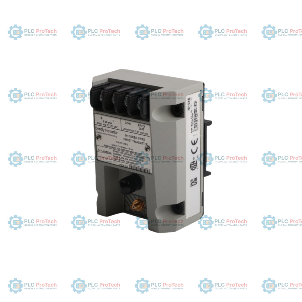
Le Bently Nevada 991-25-50-01-01 est un transmetteur de poussée alimenté en boucle à deux fils, conçu pour mesurer la position axiale relative d’un arbre de machine tournante. Il accepte une entrée directe d’une sonde de proximité 3300 NSv et d’un câble d’extension, transformant le signal de proximité en une sortie de courant proportionnelle de 4 à 20 mA. Cet appareil s’intègre directement aux automates programmables (PLC), systèmes de contrôle distribués (DCS) et réseaux SCADA pour fournir une protection continue des machines et une surveillance de l’état. Les applications industrielles typiques incluent les compresseurs d’air centrifuges, petites pompes, moteurs et ventilateurs avec paliers à film fluide où un rack complet de surveillance de protection des machines n’est pas nécessaire.
Caractéristiques
Sortie de courant en boucle 4 à 20 mA alimentée par deux fils
Conçu pour la mesure sans contact du déplacement axial d’arbre
Compatible avec la sonde de proximité 3300 NSv et câble d’extension
Connecteur BNC intégré pour accès au signal de vibration dynamique et diagnostics
Configurations de montage sur rail DIN ou panneau
Réglages zéro et étendue non interactifs
Construction moulée pour environnements à forte humidité jusqu’à 100 % de condensation
Circuit Not OK/Signal Defeat pour éviter les fausses alarmes dues à des sondes de proximité défectueuses ou des connexions lâches
Applications
Compresseurs d’air centrifuges
Pompes de process et moteurs industriels
Turbines à vapeur et à gaz
Moteurs électriques avec paliers à poussée
Ventilateurs et soufflantes de tours de refroidissement
Informations de commande
Code d’option
Description
991
Transmetteur de poussée
25
Option pleine échelle : 25-0-25 mils
50
Option de longueur du système : 5,0 mètres (16,4 pieds)
01
Option de montage : clips sur rail DIN 35 mm
01
Option d’approbation d’agence : CSA Division 2
Spécifications techniques
Catégorie
Paramètre
Spécification
Fabricant
Marque
Bently Nevada
Origine
Pays d’origine
États-Unis
Physique
Poids approximatif
0,43 kg
Dimensions (H x L x P)
53,3 mm x 73,9 mm x 100,1 mm (2,10 po x 2,91 po x 3,94 po)
Hauteur du corps (sans clip DIN)
42,6 mm (1,68 po)
Distance des trous de montage (largeur x longueur)
63,5 mm x 69,9 mm (2,50 po x 2,75 po)
Diamètre du trou de montage
5,8 mm (0,23 po)
Électrique
Plage de tension d’entrée
12 à 35 Vdc (au bornier de l’émetteur)
Sortie de courant
4 à 20 mA (linéaire sur une plage de 50 mils)
Précision de la boucle
Dans ±1,5 % sur la plage pleine échelle spécifiée
Résistance maximale de la boucle
1000 ohms y compris câble à 35 Vdc
Limitation de courant
23 mA typique
Dynamique
Réponse en fréquence
DC à 10 Hz
Sortie connecteur BNC
Tension brute de la sonde de proximité mise en tampon (Nominal 200 mV/mil)
Taille minimale de la cible
Diamètre de 9,5 mm
Environnemental
Température de fonctionnement
-35 à +85 degrés Celsius
Température de stockage
-51 à +100 degrés Celsius
Humidité relative
100 % condensation, non submergé
Connexions/Interfaces
Bornier / Connecteur
Fonction
PROX
Connexion de la sonde de proximité
COM
Commun du signal / Masse système
+4-20mA
Sortie positive de boucle de puissance / courant
-4-20mA
Sortie négative de boucle de puissance / courant
BNC
Sortie de signal dynamique (tension de proximité tamponnée)
Directives d'installation
Dimensions et montage
Le module accepte à la fois les options de montage sur panneau (cloison) et sur rail DIN. Lors de l'utilisation de la configuration de montage sur panneau, préparez quatre trous de fixation avec un espacement de 63,5 mm (largeur) par 69,9 mm (longueur). Utilisez les trous de fixation standard de 5,8 mm de diamètre ou les vis fournies 6-32 x 1,326 pour une fixation sécurisée sur cloison. Pour les configurations sur rail DIN, assurez-vous qu'un rail DIN standard de 35 mm est solidement installé avant de clipser les attaches de montage DIN du transmetteur.
Mise à la terre et blindage
Une mise à la terre correcte est essentielle pour minimiser les interférences de bruit. Le transmetteur doit être monté sur une plaque mise à la terre ou un rail DIN mis à la terre. Assurez-vous que la tresse de blindage du câble est mise à la terre à une seule extrémité, généralement côté salle de contrôle/DCS, pour éviter les boucles de terre.
Réglage de l'écart de la sonde
Avant la mise en service finale, la sonde de proximité doit être positionnée physiquement (écartée) par rapport à la cible de l'arbre. Ajustez l'écart jusqu'à ce que la sortie du transmetteur affiche environ 12 mA, ce qui correspond au point médian de la plage linéaire de poussée (0 mils).
Acheminement des câbles
Faites passer les câbles de la sonde et de la boucle dans des conduits métalliques dédiés et mis à la terre ou dans des chemins de câbles. Évitez de faire passer les câbles du transmetteur parallèlement aux lignes d'alimentation AC haute tension ou aux circuits de commutation de machines lourdes pour prévenir les interférences électromagnétiques (EMI).
Précautions en zone dangereuse
Lorsqu'il est installé dans des zones classées, des barrières de sécurité intrinsèque appropriées ou des boîtiers antidéflagrants doivent être utilisés conformément aux codes électriques locaux et aux plans d'installation spécifiques fournis par le fabricant.
FAQ
Quelle est la fonction principale de ce transmetteur de poussée ?
Il mesure le déplacement axial ou la position de poussée d'un arbre de machine tournante par rapport à un point de référence fixe à l'aide d'une sonde de proximité sans contact.
Quel type de système de sonde est compatible avec ce transmetteur ?
Il est conçu spécifiquement pour s'interfacer avec une sonde de proximité Bently Nevada 3300 NSv et un système de câble d'extension.
Comment l'appareil est-il alimenté ?
C'est un appareil alimenté par boucle fonctionnant sur une alimentation de 12 à 35 Vcc connectée via la boucle de courant 4 à 20 mA.
Que fournit le connecteur BNC ?
Le connecteur BNC fournit un signal de tension brut tamponné proportionnel à la distance de l'écart de la sonde, permettant aux ingénieurs de connecter des équipements de diagnostic comme des oscilloscopes ou des analyseurs sans déconnecter la boucle.
Cet appareil peut-il être utilisé pour des mesures de vibrations radiales ?
Non, ce modèle spécifique est configuré et calibré pour la mesure de position de poussée (axiale). Pour les vibrations radiales, un transmetteur de vibration 990 doit être utilisé.
Quelle est la fonction du circuit Not OK/Signal Defeat ?
Le circuit force la sortie du signal à descendre en dessous de 3,6 mA dans les 100 microsecondes suivant une défaillance de la sonde ou une connexion lâche afin d'éviter les fausses alarmes dans le système de contrôle.
Technical Datasheet (PDF)Complete specifications and technical drawings.
Expédition express mondiale
Livraison standard : 4 à 6 jours ouvrables via DHL, FedEx et UPS.
Expédition express : Expédition le jour même pour les commandes en stock passées avant 14h00 (GMT+8).
Couverture mondiale : Service dans plus de 150 pays, avec livraison rapide en Arabie Saoudite et aux Émirats Arabes Unis.
Retours et garantie
Garantie de 30 jours : Retours acceptés pour les produits en stock dans leur emballage d'origine scellé en usine.
Garantie de 12 mois : Chaque composant industriel est couvert par notre garantie technique professionnelle.
Les commandes sont traitées et livrées du lundi au vendredi (hors jours fériés).
Pour connaître l'éligibilité complète, les frais de restockage et les détails des retours internationaux, veuillez consulter notre site officiel
Politique de remboursement et de retour
.
Les données de maintenance relient les ordres de travail, les signaux des capteurs, l'historique des actifs, les coûts et les connaissances des techniciens. Bien utilisées, elles améliorent la...
Cet article explique comment les actionneurs électriques intégrés, tels que la série e-Actuator de SMC, transforment le contrôle de mouvement industriel en remplaçant les systèmes pneumatiques et...
Cet article explique comment les systèmes PLC réalisent les opérations mathématiques de base telles que l'addition, la soustraction, la multiplication, la division, le modulo et l'exponentiation dans...
L'article explique plusieurs fonctions avancées de logique booléenne utilisées en programmation d'automates programmables industriels (API) au-delà des opérations de base ET, OU et NON. Il couvre...
La logique booléenne est la base de tout programme PLC. Des commandes machines simples aux systèmes d'automatisation industrielle complexes, les portes logiques déterminent comment les contrôleurs...
Les pare-feux industriels jouent un rôle crucial dans la cybersécurité OT, protégeant les réseaux PLC, DCS et SCADA grâce à la segmentation, au contrôle des entrées/sorties et à l’intégration IDS/IPS...
Choisir une sélection entraîne un rafraîchissement complet de la page.