Description
Le Bently Nevada 991-25-70-03-05 L'émetteur de poussée 991 est un émetteur de déplacement axial à deux fils, alimenté par boucle, conçu principalement pour les fabricants d'équipements d'origine (OEM) de compresseurs d'air centrifuges, petites pompes, moteurs ou ventilateurs. L'appareil accepte une entrée unique d'une sonde de proximité 3300 NSv et de son câble d'extension assorti, conditionnant le signal en une sortie standard industrielle de boucle de courant de 4 à 20 mA proportionnelle à la position axiale de l'arbre (poussée) pour une intégration directe dans les systèmes de contrôle des machines pour la protection et l'alarme.
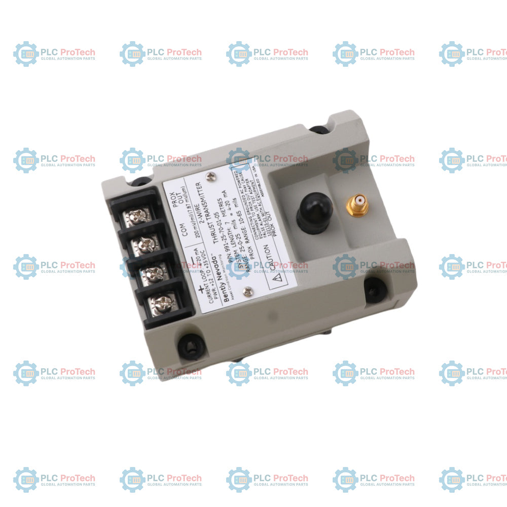
L'émetteur intègre la fonctionnalité d'un capteur Proximitor en une seule unité, éliminant le besoin d'un capteur indépendant externe. Les bornes PROX OUT et COM non isolées, ainsi que le connecteur coaxial BNC, fournissent un signal de vibration dynamique et de tension d'écart pour le diagnostic des machines. L'émetteur présente une construction entièrement noyée, permettant un fonctionnement stable dans des environnements à forte humidité jusqu'à 100 % de condensation.
Caractéristiques
- Le design intégré combine l'émetteur et le capteur Proximitor en une seule unité.
- La configuration standard à 2 fils, alimentée par boucle, fournit un signal de 4 à 20 mA continu proportionnel au déplacement axial à pleine échelle.
- Les bornes PROX OUT non isolées, COM et le connecteur BNC fournissent des sorties de vibration dynamique et de tension d'écart pour le diagnostic sur le terrain.
- Des potentiomètres externes de zéro et d'étendue non interactifs sous l'étiquette facilitent le réglage de la boucle.
- La broche Test Input permet une vérification rapide de la sortie du signal de boucle à l'aide d'une source de tension continue variable.
- Le circuit Power-up Inhibit élimine les erreurs de signal causées par les transitoires de tension lors du démarrage.
- Le circuit Not OK / Signal Defeat bride la sortie en dessous de 3,6 mA pour éviter les sorties élevées ou les fausses alarmes causées par des défauts de sonde ou de câble.
- Le boîtier entièrement noyé permet une utilisation en environnements à forte humidité et à condensation à 100 %.
- La configuration standard comprend des clips de rail DIN de 35 mm et du matériel de montage sur cloison.
Applications
- Compresseurs d'air centrifuges
- Petites pompes industrielles
- Moteurs électriques industriels
- Ventilateurs industriels de ventilation
- Surveillance de la tendance de la position axiale du rotor (poussée) et protection des machines
Spécifications techniques
Configuration du modèle (991-25-70-03-05)
Basé sur la nomenclature de la série Bently Nevada 991, les paramètres spécifiques de configuration du modèle sont décodés comme suit :
| Position de l'option |
Élément de configuration |
Spécification technique |
| AA |
Option à pleine échelle |
25-0-25 mils |
| BB |
Option de longueur du système |
7,0 mètres (23,0 pieds) |
| CC |
Option de montage |
Clips et vis DIN |
| DD |
Option d'approbation d'agence |
CSA Division 2, ATEX Zone 0, ATEX Zone 2, y compris approbation maritime ABS |
Électrique
| Paramètre |
Spécification |
| Alimentation électrique |
Nécessite +12 à +35 Vcc aux bornes de l'émetteur |
| Sortie du signal |
4 à 20 mAcc, configuration 2 fils |
| Précision de la boucle |
Typique ±1,5 % sur la plage pleine échelle spécifiée (mesuré de l'entrée TEST à une résistance de boucle de 250 ohms) |
| Résistance maximale de la boucle |
1 000 ohms maximum à 35 Vcc (y compris la résistance du câble). Formule : R_LOOP = 43,5 x (V_PS - 12) ohms |
| Limitation de courant |
23 mA typique |
| Impédance de sortie dynamique |
PROX OUT a une impédance de sortie de 10 kohms, calibrée pour une charge de 10 Mohms |
| Plage linéaire |
0,25 à 1,65 mm (10 à 65 mils) à l'interface PROX OUT |
| Facteur d'échelle incrémental |
7,87 mV/micromètre (200 mV/mil) typique, ±6,5 % incluant l'erreur d'interchangeabilité mesurée sur une cible plate en acier AISI 4140 |
| Stabilité thermique |
Le facteur d'échelle incrémental reste dans ±10 % de 7,87 mV/micromètre (200 mV/mil) de 0 °C à +70 °C |
| Taille minimale de la cible |
Diamètre de 9,5 mm (0,375 in) |
Dynamique et temporisation
| Paramètre |
Spécification |
| Délai Not OK |
La sortie du signal chute en dessous de 3,6 mA en moins de 100 microsecondes après l'apparition d'une condition Not OK |
| Temps de récupération OK |
La sortie du signal revient à la normale en moins de 0,1 seconde après la suppression de la condition Not OK |
Limites environnementales
| Paramètre |
Spécification |
| Température de fonctionnement de l'émetteur |
-35 °C à +85 °C |
| Température de stockage de l'émetteur |
-51 °C à +100 °C |
| Température de fonctionnement de la sonde |
-52 °C à +177 °C |
| Température de stockage de la sonde |
-52 °C à +177 °C |
| Humidité relative |
100 % condensation, fonctionnement non immergé (les connecteurs coaxiaux doivent être protégés) |
Mécanique
| Paramètre |
Spécification |
| Poids de l'émetteur |
0,43 kg (0,9 lbm) |
| Poids total du système |
0,82 kg (1,8 lbm) typique |
| Matériau du boîtier de l'émetteur |
Acier inoxydable AISI 303 ou 304 (SST) |
| Matériau de la pointe de la sonde |
Polysulfure de polyphénylène (PPS) |
| Câble de sonde |
Câble coaxial 75 ohms, isolation en fluoréthylène propylène (FEP) |
| Résistance à la traction |
222 N (50 lbf) maximum entre le boîtier de la sonde et le câble de la sonde |
Connexions / Interfaces
Blocs de bornes et connecteurs de l'émetteur
| Bloc de bornes / Connecteur |
Nom de la borne |
Fonction |
| E1 |
PWR (Alimentation) |
Entrée d'alimentation positive de la boucle 4-20 mA (+17 à +35 Vcc) |
| E2 |
COM (Commun) |
Boucle 4-20 mA négative / retour commun |
| E3 |
PROX OUT |
Sortie de signal dynamique non isolée (maximum 3 mètres de câble à paire torsadée) |
| E4 |
COM |
Référence commune du signal dynamique |
| J2 |
PROX OUT (BNC) |
Sortie coaxiale dynamique non isolée BNC pour équipement de diagnostic portable |
| J3 |
Connecteur de sonde |
Prise coaxiale ClickLoc pour connecter le câble d'extension de la sonde de proximité |
Directives d'installation
- Choix du câble : Pour la boucle de courant 4 à 20 mA entre le transmetteur et le récepteur (PLC/DCS), utilisez un câble blindé à paires torsadées de 1,0 mm² (18 AWG) (numéro de pièce 02173006). La longueur maximale autorisée est de 13 km (8 miles).
- Mise à la terre et blindage : Le blindage du câble doit être relié à une terre à point unique à l'extrémité réceptrice. Le blindage à l'extrémité du transmetteur doit être isolé et séparé du boîtier du transmetteur et de la terre locale pour éviter les boucles de terre.
- Isolation de l'interface PROX OUT : Le connecteur coaxial PROX OUT et les bornes ne sont pas isolés de la boucle 4 à 20 mA. Connecter directement un équipement de test alimenté en courant alternatif et mis à la terre (comme un oscilloscope ou un analyseur) à PROX OUT peut court-circuiter la boucle ou introduire des courants de terre, provoquant de fausses alarmes ou déclenchements de poussée. Utilisez l'adaptateur de test 122115-01 pour les équipements alimentés en courant alternatif.
- Caractéristiques de phase du signal : La phase du signal dynamique PROX OUT est inversée par rapport aux capteurs Proximitor standard de Bently Nevada. L'adaptateur de test 122115-01 inverse le signal pour rétablir la polarité standard pour les équipements de diagnostic externes.
- Limites d'engagement des filetages : Assurez un engagement correct des filetages lors du montage de la sonde (par exemple, engagement maximal de 0,375 pouce pour les filetages 1/4-28, et 0,563 pouce pour les filetages 3/8-24). Dépasser 1,5 fois le diamètre nominal du filetage peut provoquer un blocage interne et endommager le boîtier.
- Protection contre l'humidité : Bien que le boîtier du transmetteur soit conçu pour une humidité relative de condensation à 100 %, il ne doit pas être immergé. Tous les connecteurs coaxiaux externes doivent être scellés à l'aide de protections ClickLoc (comme des manchons en fluorosilicone) pour empêcher l'entrée d'humidité ou d'huile.
- Restrictions sur la résistance de boucle : Vérifiez que la résistance totale de la boucle, R_LOOP, ne dépasse pas la valeur maximale autorisée par la tension d'alimentation. Si la résistance de la boucle est trop élevée, le transmetteur ne pourra pas fournir la sortie complète de 20 mA dans les conditions de déplacement maximal.
Conformité et certifications
- FCC : Conforme aux règles FCC Partie 15.
- ATEX : Conforme à la directive ATEX 2014/34/UE.
- RoHS : Conforme à la directive RoHS 2011/65/UE.
- China RoHS : La durée d'utilisation respectueuse de l'environnement (EFUP) est évaluée à 15 ans selon SJ/T 11364-2014.
- Maritime : Approuvé selon les règles ABS 2009 pour navires en acier.
- Homologations de sécurité Canada et États-Unis (cNRTLus) :
- Classe I, Division 2, Groupes A, B, C, D ; T5 à Ta = +85 °C, Type 4 (lorsqu'installé selon le dessin 128838).
- Certifications pour zones dangereuses (ATEX/IECEx) :
- II 1G Ex ia IIC T4 Ga, T4 à Ta = -30 °C à +85 °C.
- II 3G Ex ec IIC T4 Gc, T4 à Ta = -30 °C à +85 °C.
- Paramètres de sécurité intrinsèque (Zone 0/1) :
- Bornes E1-E2 (Alimentation/Boucle) : U_i = 28 V, I_i = 120 mA, P_i = 0,84 W, C_i = 20 nF, L_i = 10 microhenrys.
- Bornes E3-E4 et connecteur J2 (Sortie Prox) : U_o = 28 V, I_o = 6 mA, P_o = 0,17 W, C_o = 80 nF, L_o = 1 H.
- Interface J3 (Connexion de sonde) : U_o = 28 V, I_o = 100 mA, P_o = 0,8 W, C_o = 27,3 nF, L_o = 5,3 mH.
FAQ
Q1 : Quelles sont les principales limitations fonctionnelles logiques de l’émetteur 991 par rapport aux systèmes de surveillance standard comme la série 3500 ?
A1 : L’émetteur 991 n’inclut pas de logique de surveillance complexe telle que la désactivation du canal Timed OK, le Danger Bypass ou le Trip Multiply. Sa sortie analogique 4-20 mA empêche également une intégration directe au niveau logiciel avec des plateformes de gestion d’actifs d’usine comme System 1 ou Rule Paks.
Q2 : Quelle est la plage de mesure calibrée pour la configuration 991-25-70-03-05 ?
A2 : L’option de plage « 25 » signifie une plage de mesure linéaire pleine échelle de 25-0-25 mils de déplacement axial cartographiée sur la boucle de courant 4 à 20 mA.
Q3 : Quelle longueur totale de système est requise pour cette configuration spécifique ?
A3 : L’option de longueur de système « 70 » impose que l’émetteur soit utilisé exclusivement avec un système combiné de sonde de proximité 3300 NSv et câble d’extension de 7,0 mètres (23,0 pieds). Mélanger des composants de système de 5,0 mètres dégradera la calibration et la linéarité.
Q4 : Que se passe-t-il si un oscilloscope alimenté en courant alternatif est connecté directement à la prise BNC PROX OUT ?
A4 : Comme la masse du connecteur PROX OUT est partagée avec le retour de la boucle 4-20 mA (COM), connecter un instrument alimenté en courant alternatif avec une masse commune peut créer des boucles de masse ou provoquer un court-circuit, entraînant de fausses alarmes de poussée ou des arrêts de machines au niveau du système de contrôle.
Q5 : Comment connecter en toute sécurité des instruments de diagnostic alimentés en courant alternatif externes ?
A5 : Utilisez l’adaptateur de test Bently Nevada 122115-01. Cet adaptateur assure l’isolation entre le circuit de l’émetteur et l’instrument de test pour éliminer les boucles de masse tout en inversant le signal de 180 degrés afin de correspondre à la polarité standard de l’instrument.
Q6 : Quel est le temps de réponse dynamique de la boucle de courant 991 lors d’une panne du capteur ?
A6 : Si une sonde ou un câble en circuit ouvert/court-circuit provoque un état Not OK, le courant de sortie chute en dessous de 3,6 mA en moins de 100 microsecondes. Une fois la panne résolue, la boucle revient à un état OK en moins de 0,1 seconde.
Q7 : Comment la tension d’alimentation affecte-t-elle la capacité de résistance de la boucle de l’émetteur ?
A7 : L’émetteur nécessite entre +12 Vcc et +35 Vcc à ses bornes. La résistance maximale admissible de la boucle (y compris le câblage et les barrières de sécurité) est déterminée par la formule : R_LOOP = 43,5 x (V_PS - 12) ohms. Une tension insuffisante ou une résistance élevée limitera le courant maximal de sortie en dessous de 20 mA.
Q8 : Quelle est la fonction de la broche Test Input sur l’émetteur ?
A8 : La broche Test Input permet aux techniciens d’appliquer une source de tension continue variable externe pour simuler les variations d’écart de la sonde. Cela permet de vérifier la boucle et l’alarme dans le système de contrôle sans retirer ni ajuster la sonde de proximité physique.
Q9 : Les potentiomètres Zéro et Étendue s’influencent-ils mutuellement lors de l’étalonnage ?
A9 : Non, l’émetteur utilise des potentiomètres non interactifs. Ajuster la position zéro ne modifie pas la pente de l’étendue, et ajuster l’étendue ne déplace pas le point zéro, ce qui simplifie le processus d’étalonnage.
Q10 : Quelle est la distance maximale admissible pour le câblage de sortie en boucle ?
A10 : En utilisant le câble torsadé blindé recommandé de 1,0 mm² (18 AWG) et une alimentation 35 Vcc, le signal du circuit de courant peut être transmis jusqu’à une distance maximale de 13 km (8 miles).
Q11 : Ce modèle spécifique peut-il être installé dans des sites industriels dangereux ?
A11 : Oui, l’option d’approbation « 05 » fournit une certification multi-agences. L’appareil peut être installé dans des environnements de Classe I, Division 2 ou utilisé comme dispositif intrinsèquement sûr (Ex ia IIC T4 Ga) en zones 0/1 lorsqu’il est câblé via une barrière de sécurité approuvée.
Q12 : Pourquoi l’émetteur 991 doit-il être associé à une sonde 3300 NSv plutôt qu’à une sonde standard de 8 mm ?
A12 : Le circuit de conditionnement interne de l'émetteur 991 est calibré pour les caractéristiques électriques et physiques de la sonde 3300 NSv, conçue pour des jeux serrés et de petits alésages. Connecter une sonde de 8 mm entraînera des erreurs importantes du facteur d'échelle.
Q13 : Quelle protection est requise pour les connexions coaxiales en environnements humides ?
A13 : Bien que le corps de l'émetteur soit entièrement encapsulé contre une humidité condensante à 100 %, les connecteurs coaxiaux ClickLoc entre la sonde et le câble d'extension peuvent subir une atténuation du signal s'ils sont exposés à l'humidité ou à l'huile. Ils doivent être protégés avec des protecteurs de connecteurs en fluorosilicone.