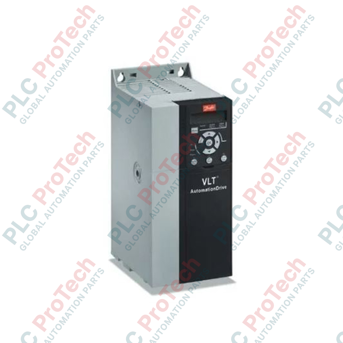
Présentation du produit
Le 134F2975 (FC-360H2K2T4E20H2BXCDXXSXXXXAXBX) est un variateur de fréquence robuste de la série Danfoss VLT AutomationDrive FC-360, conçu avec précision pour des applications industrielles à forte charge. Ce variateur, d’une puissance nominale de 2,2 kW (3,0 HP), constitue un élément clé des systèmes d’automatisation nécessitant une grande stabilité de couple et un contrôle précis du moteur, tels que les convoyeurs industriels, les mélangeurs et les machines de traitement. En intégrant une technologie avancée, le 134F2975 réduit efficacement les contraintes mécaniques sur le matériel connecté et optimise la consommation d’énergie. Son circuit imprimé revêtu garantit une intégrité opérationnelle à long terme, même dans des environnements où la poussière ou l’humidité pourraient compromettre les composants électroniques sensibles, en faisant un atout essentiel pour minimiser les maintenances imprévues.
Configuration technique
L’architecture FC-360 est conçue pour des lignes de production exigeantes nécessitant une grande fiabilité et une réponse rapide du contrôle. Cette unité est équipée d’un freinage par hacheur intégré, facilitant une décélération contrôlée pour les charges à forte inertie. Configuré avec un boîtier IP20, le variateur est optimisé pour une installation en armoire, offrant une intégration peu encombrante. Il dispose de la fonction Loadsharing, permettant la gestion énergétique entre plusieurs variateurs afin de maximiser l’efficacité globale du système. Le variateur supporte une alimentation triphasée 380-480 VAC, assurant une large compatibilité avec les réseaux électriques industriels standards. Bien que cette unité soit fournie sans affichage local, sa carte de contrôle standard permet une intégration fluide dans des réseaux PLC ou DCS de niveau supérieur pour la surveillance à distance et la gestion des paramètres.
Caractéristiques techniques
| Caractéristique |
Spécification |
| Modèle |
134F2975 |
| Marque |
Danfoss |
| Série |
VLT AutomationDrive FC-360 |
| Puissance nominale |
2,2 kW / 3,0 HP |
| Surcharge |
Surcharge élevée |
| Phases |
Triphasé |
| Tension d’alimentation |
380 - 480 VAC |
| Boîtier |
IP20 |
| Filtre RFI |
Classe A2 |
| Hacheur de freinage |
Intégré |
| Revêtement PCB |
Revêtu |
| Poids |
2,64 kg |
| Poids à l’expédition |
5 kg |
FAQ
Quel est l’avantage du hacheur de freinage intégré dans ce modèle ?
Le hacheur de freinage permet au variateur de dissiper l’énergie générée par le moteur lors de la décélération ou du freinage. Cela est crucial pour les applications impliquant des charges à forte inertie, évitant ainsi les défauts de surtension sur le bus continu.
Le 134F2975 peut-il être surveillé sans affichage local ?
Oui. Étant donné que l’unité ne dispose pas d’un affichage intégré, toute surveillance et configuration doivent être effectuées via une connexion à distance ou en interfaçant le variateur via un bus de terrain avec votre système de contrôle principal.
Comment fonctionne la fonction Loadsharing ?
La fonction Loadsharing (option D) permet de connecter le bus continu du variateur à d’autres variateurs compatibles. Cela facilite l’échange d’énergie entre variateurs dans un système, où un variateur agissant en générateur peut fournir de l’énergie à un autre variateur agissant en moteur.
Bonnes pratiques d’ingénierie et installation
-
Dissipation thermique : Assurez-vous que le variateur est installé dans un environnement où la température ambiante ne dépasse pas les limites spécifiées par le fabricant. Maintenez un dégagement vertical minimum de 100 mm au-dessus et en dessous de l’unité pour faciliter le flux d’air nécessaire aux dissipateurs internes.
-
Blindage et mise à la terre : Pour minimiser les émissions rayonnées et garantir la conformité à la norme RFI Classe A2, utilisez toujours des câbles moteurs blindés. Le blindage doit être connecté à 360 degrés au châssis à l’aide de colliers de serrage conducteurs, tant au niveau du variateur que de la boîte à bornes du moteur.
-
Sélection des câbles : Pour l’alimentation 380-480 VAC, assurez-vous que les câbles d’alimentation sont dimensionnés conformément aux normes électriques locales pour la puissance spécifiée. Utilisez des embouts appropriés pour les connexions aux bornes afin d’assurer un contact mécanique sécurisé et à faible résistance.