Description
Facilitating seamless machine-to-operator interaction, the Delta Electronics DOP-B07S411 serves as a robust 7-inch widescreen operator panel engineered for harsh industrial environments. Operating on a high-speed 32-bit RISC processor, this terminal provides highly responsive touch execution and vivid graphical rendering of machine statuses. The onboard storage accommodates complex runtime projects, historical event logging, and extensive recipe storage, making it a reliable terminal for decentralized control systems.
Key Features
-
High-Resolution Display: Widescreen 7-inch TFT LCD with 800 x 480 resolution supporting up to 65,536 colors.
-
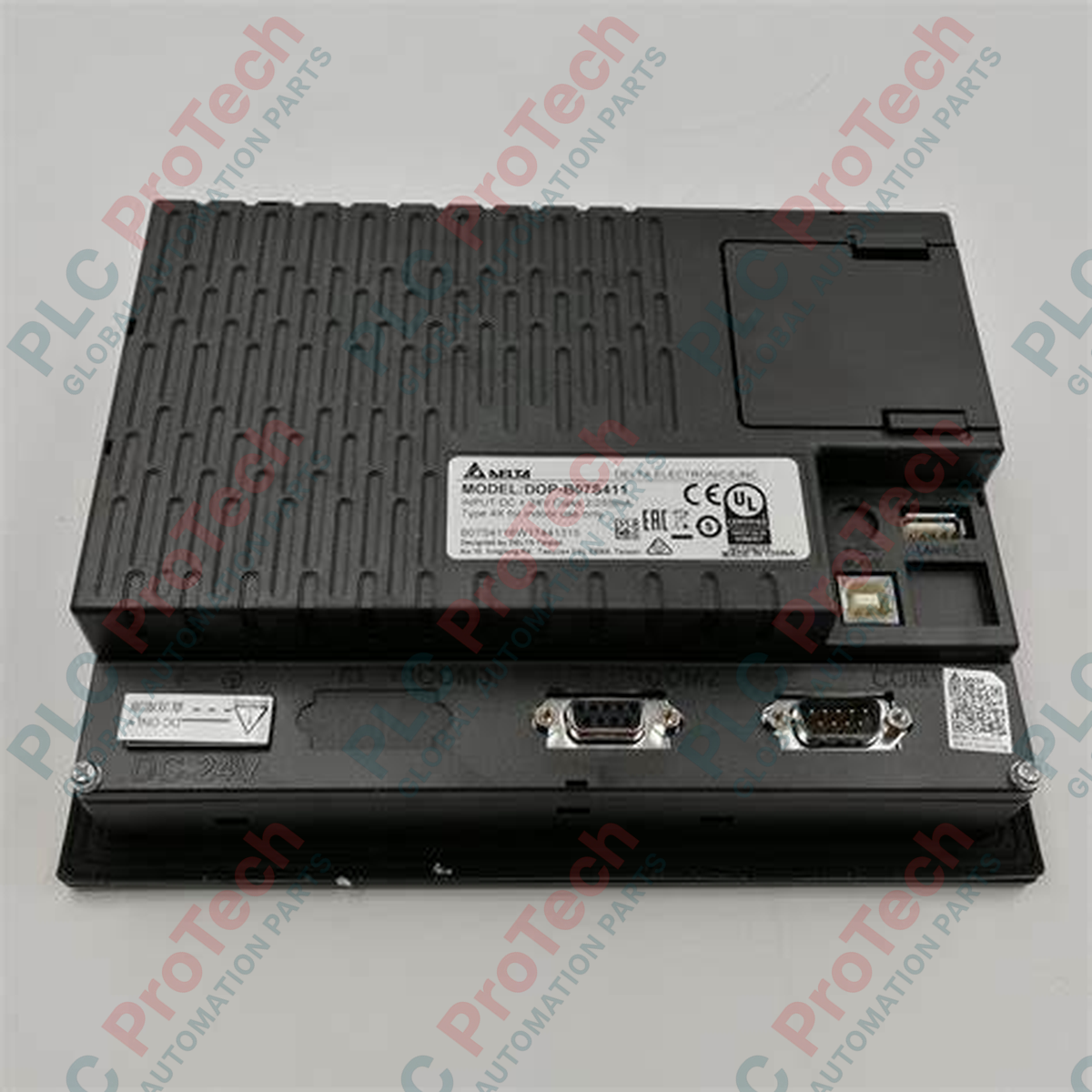
Flexible Connectivity: Three physical COM ports configured to support RS-232, RS-422, and RS-485 topologies simultaneously.
-
Expansion Options: Built-in SD card slot and USB Host port for quick project transfers, recipe management, and external peripheral interfaces.
-
Robust Front Panel: IP65/NEMA 4 rating ensures total protection against dust and low-pressure water jets.
-
Flexible Orientation: Native support for both landscape (horizontal) and portrait (vertical) mounting configurations.
Applications
- Machine tool sequencing and CNC status monitoring.
- Packaging machinery and automated pick-and-place lines.
- HVAC ventilation systems and municipal pumping stations.
- Integrated PLC networks within assembly line configurations.
Technical Specifications
| Parameter |
Specification |
| Manufacturer |
Delta Electronics |
| Model Number |
DOP-B07S411 |
| Series |
DOP-B Series |
| Display Size |
7 inches (Diagonal) |
| Display Type |
TFT LCD (65,536 colors) |
| Resolution |
800 x 480 pixels |
| Processor Type |
32-bit RISC Microcontroller |
| Flash ROM |
128 MB |
| Operating Voltage |
24 VDC (allowable range: 24 VDC -15% to +10%) |
| Power Consumption |
5.0 Watts Max |
| COM Ports |
COM1 (RS-232), COM2 (RS-232/RS-485), COM3 (RS-422/RS-485) |
| USB Interfaces |
1 USB Client Ver 2.0 (data download); 1 USB Host Ver 1.1 (peripherals) |
| Expansion Slot |
SD Card (supports SDHC) |
| Operating Temperature |
0 to 50 degC |
| Front Panel Protection |
IP65 / NEMA 4 waterproof and dustproof |
| Country of Origin |
Taiwan |
| Net Weight |
1.0 kg |
| Shipping Weight (Calculated) |
1.5 kg (Standard boxed weight) |
| Package Dimensions (Calculated) |
245 mm x 195 mm x 85 mm |
Connections and Interfaces
| Connector / Interface |
Signal / Circuit Pin Assignment |
| COM1 (9-Pin D-Sub Male) |
Pin 2: RXD, Pin 3: TXD, Pin 5: GND (RS-232 Configuration) |
| COM2 (9-Pin D-Sub Male) |
Pin 1: D+, Pin 6: D- (RS-485 Differential Pair) / RS-232 shared lines |
| COM3 (9-Pin D-Sub Male) |
Pin 4: RXD+, Pin 9: RXD-, Pin 8: TXD+, Pin 3: TXD- (RS-422 Configuration) |
| 24V DC Input Terminal |
Pin 1: +24V, Pin 2: 0V, Pin 3: FG (Frame Ground) |
Empirical Engineering Insights
Alternative Models & Compatibility
The DOP-B07S411 is a legacy operator panel. For modern system deployments or standard physical drop-in replacements, system designers should evaluate the newer DOP-107BV or DOP-107CV units. While the cutout dimensions are matching, the configuration must be upgraded from DOPSoft v2.xx to DOPSoft v4.00 series. Comms configurations convert smoothly, but script macros must be fully re-validated post-conversion.
Application Pitfalls & Engineering Notes
When driving heavy operations, ensure that the current draw from the USB Host port does not exceed 500mA. Attempting to power heavy external hard drives directly from the port can cause the HMI controller board to reset under low-voltage fault conditions. In highly dynamic thermal environments, maintaining continuous operating temperatures near 50 degC will degrade the fluorescent backlighting tube lifespan rapidly; configure the integrated backlight saver auto-timeout parameter within DOPSoft to mitigate local heat build-up.
Commissioning & Wiring Tips
To avoid operational communication faults, isolate the HMI's 24V DC feed using a dedicated switch-mode power supply separate from inductive loads like solenoids or contactors. Ensure that the FG terminal is connected directly to a clean instrumentation ground. Standard industrial RS-485 drops exceeding 50 meters must feature a 120-ohm termination resistor placed across the D+ and D- lines at both ends of the segment.
Installation Guidelines
CRITICAL WARNING:
De-energize all primary and auxiliary power lines before physically installing or removing this unit. Do not live-insert communication interfaces or wiring terminal blocks. Doing so risks electrostatic discharge or sudden electrical potential offsets that can destroy the driver ICs on the COM boards.
1
Prepare a mounting cutout exactly matching 196.8 mm x 142.9 mm on the panel door, ensuring a minimum clearance of 50 mm surrounding the cooling vents.
2
Seat the waterproof seal gasket uniformly in the rear bezel channel before sliding the terminal housing into the panel opening.
3
Install all supplied mounting brackets into their slot tracks on the panel frame and hand-tighten the tensioning screws evenly. Torque to 0.5 N-m to prevent casing damage.
4
Connect the dedicated 24V DC wiring harness and secure the COM port backshells to suppress cable-strain induced electrical disconnects.