Présentation du produit
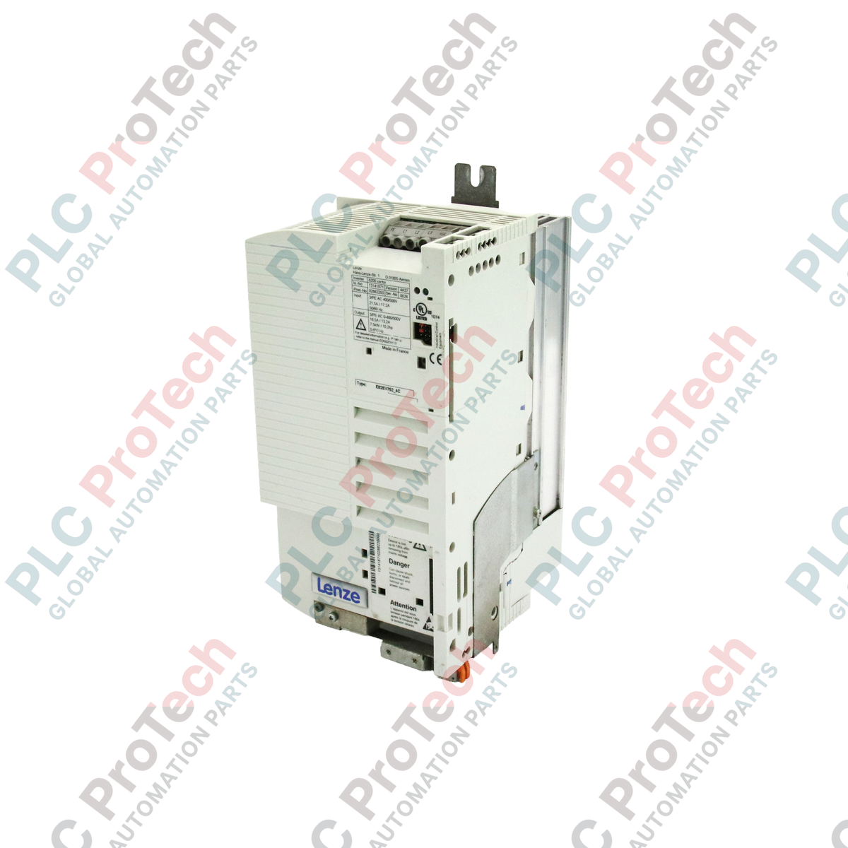
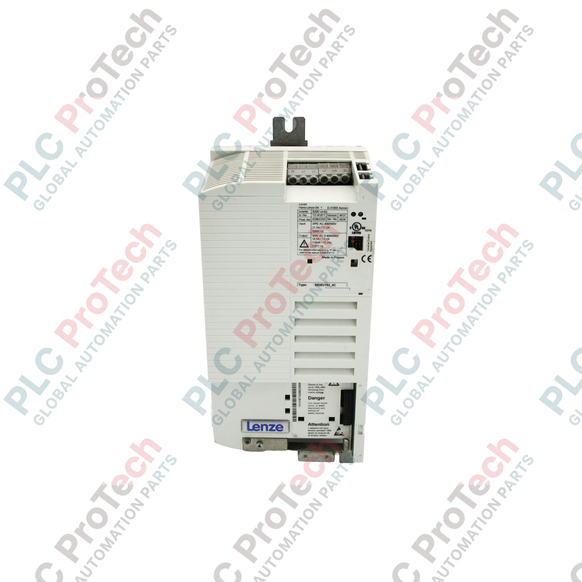
Le E82EV752_4C (E82EV752K4C) est un variateur de fréquence vectoriel haute capacité de la série 8200 conçu par Lenze pour des applications de contrôle moteur exigeantes nécessitant jusqu'à 7,5 kW (10 HP) de puissance. Fonctionnant sur une alimentation triphasée 400 / 500 VAC, ce variateur est un élément clé pour les machines industrielles lourdes, notamment les stations de pompage à grande échelle, les mélangeurs industriels à couple élevé et les lignes de convoyeurs synchronisées dans les usines de fabrication. La désignation « 4C » indique l’intégration de filtres de suppression des interférences intégrés, qui protègent le variateur contre les bruits électromagnétiques et garantissent l’intégrité des signaux de commande voisins. Avec son châssis robuste de 5,00 kg et ses caractéristiques optimisées de contrôle vectoriel, le E82EV752_4C minimise les contraintes mécaniques et maximise l’efficacité énergétique, même dans les environnements exigeants du secteur B2B mondial. Bien qu’il soit en fin de vie, il reste un composant essentiel pour la maintenance et l’optimisation des infrastructures d’automatisation existantes.
Configuration technique
Le E82EV752_4C utilise une architecture sophistiquée de contrôle vectoriel qui offre un couple de démarrage élevé et une régulation précise de la vitesse, même en conditions de charge fluctuante. Cette plateforme « Global Drive » dispose d’un emplacement modulaire pour la communication sur bus de terrain, prenant en charge des protocoles tels que PROFIBUS, CANopen et LECOM-B pour faciliter une intégration SCADA fluide. Le matériel comprend une suite complète de fonctions de protection, telles que la surveillance moteur I2t, la détection de court-circuit et la protection contre les surtensions. Son étage de puissance est conçu pour une grande fiabilité, capable de gérer des surcharges transitoires importantes. Le firmware de l’unité permet une paramétrisation avancée des rampes d’accélération/décélération en S et du freinage par injection de courant continu, assurant la douceur mécanique requise pour les processus industriels sensibles.
Caractéristiques techniques
| Caractéristique |
Spécification |
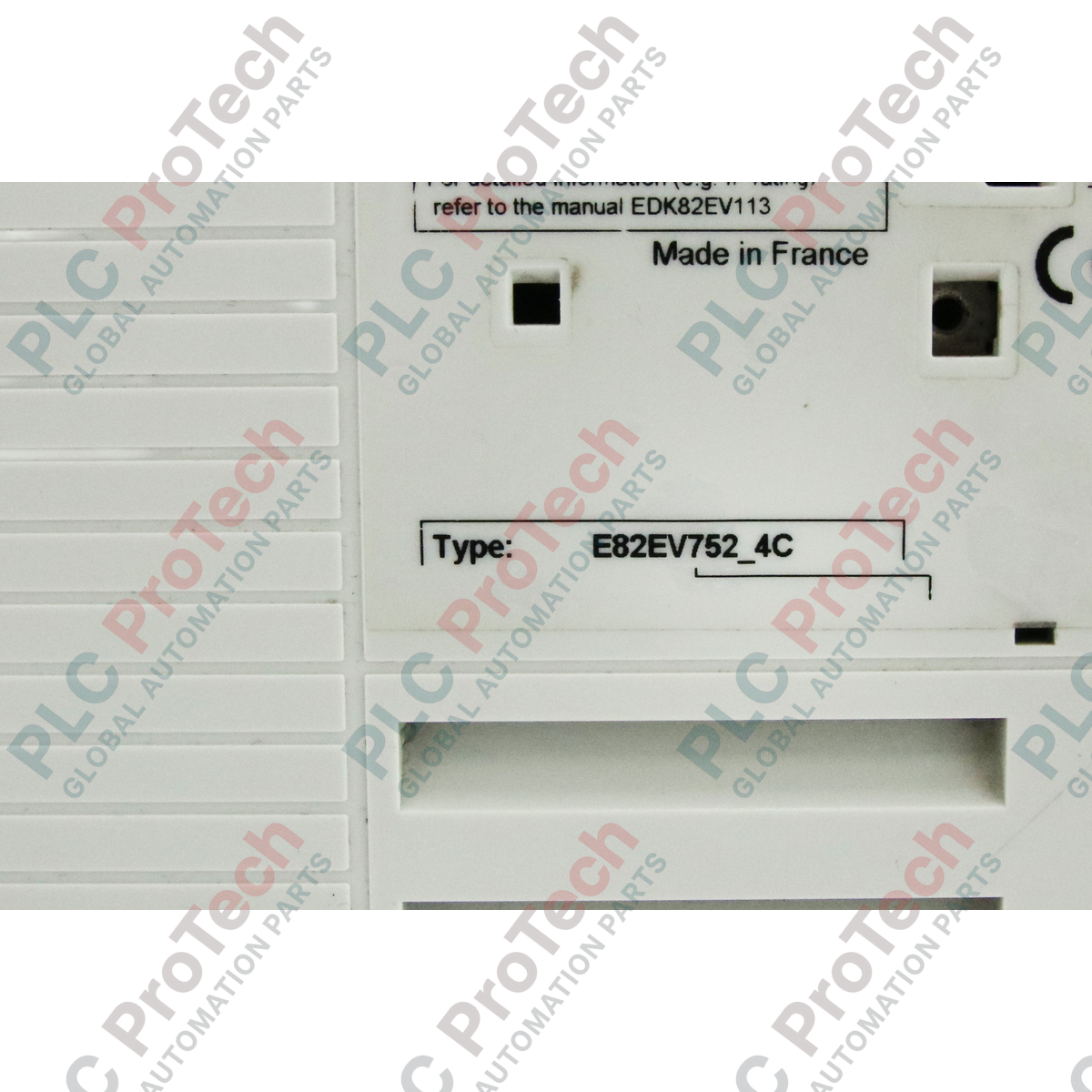
| Modèle |
E82EV752_4C / E82EV752K4C |
| Marque |
Lenze |
| Série |
8200-Series Vector |
| Puissance nominale |
7,5 kW (10 HP) |
| Tension d’entrée |
3 phases 400 / 500 VAC |
| Courant de sortie nominal |
16,5 A (à 400 V) |
| Suppression des interférences |
Filtre intégré / incorporé |
| Dimensions |
25,50 x 30,50 x 12,50 cm |
| Poids |
5,00 kg |
| Degré de protection |
IP20 |
| Température de fonctionnement |
0 à +45 °C (jusqu’à 55 °C avec réduction de charge) |
| Phase du produit |
Phase-Out |
FAQ techniques
Le E82EV752_4C prend-il en charge le freinage régénératif pour les charges à forte inertie ?
Le variateur intègre un hacheur de freinage interne ; cependant, pour les applications avec une énergie régénérative importante (comme les grands ventilateurs centrifuges), une résistance de freinage externe doit être connectée aux bornes pour dissiper l’énergie sous forme de chaleur et éviter les déclenchements « OU » (surtension).
Quelle est la principale différence entre la série 8200 et la série 9300 ?
La série 8200 est un variateur de fréquence polyvalent principalement conçu pour le contrôle de vitesse des moteurs asynchrones standards. En revanche, la série 9300 est un système servo dédié au positionnement à haute dynamique et au contrôle des moteurs synchrones.
Puis-je faire fonctionner ce variateur de 7,5 kW à une température ambiante plus élevée ?
Oui, il peut fonctionner jusqu’à 55 °C, mais vous devez appliquer une réduction de courant d’environ 2,5 % par degré Celsius au-dessus de 45 °C pour protéger l’électronique de puissance interne contre le stress thermique.
Guide d’ingénierie et d’installation
-
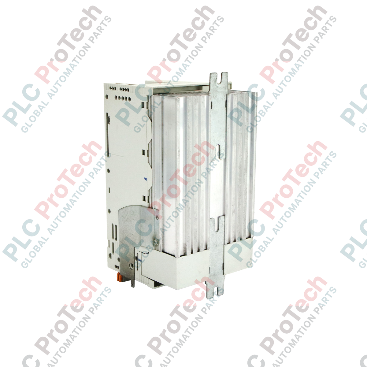
Refroidissement et circulation d’air : En raison de la puissance de 7,5 kW, cette unité génère une chaleur importante. Elle doit être montée verticalement sur une surface plane et non inflammable. Assurez un dégagement minimum de 100 mm en haut et en bas de l’unité pour permettre une circulation d’air libre à travers le dissipateur thermique.
-
Câblage conforme à la CEM : Pour maintenir l’efficacité de la suppression des interférences intégrée, utilisez uniquement des câbles moteurs blindés. Le blindage doit être connecté au rail PE à l’aide d’une pince conductrice à 360 degrés. Évitez la mise à la terre en queue de cochon, car cela augmente l’impédance haute fréquence et réduit la performance CEM.
-
Temps de décharge de sécurité : Les condensateurs du bus DC interne stockent une charge mortelle. Après avoir déconnecté l’alimentation secteur 400/500 V, attendez au moins 10 minutes avant de toucher les bornes. Vérifiez toujours que la tension entre +UG et -UG est inférieure à 50 VDC à l’aide d’un multimètre certifié avant de commencer les travaux.