Présentation du produit
Le EP1008-0002 (EP10080002) est un boîtier EtherCAT haute performance conçu pour une intégration directe sur le terrain sans besoin d'armoire de commande protectrice. Ce module d'entrée numérique 8 canaux est conçu pour capter des signaux de commande binaires au niveau du process et les transmettre, avec isolation électrique, au contrôleur d'automatisation de niveau supérieur. Optimisé pour les architectures décentralisées dans des environnements industriels exigeants tels que les lignes d'assemblage automobile, l'emballage à grande vitesse et les machines lourdes, ce module réduit considérablement la complexité du câblage et minimise la latence des signaux. En fournissant une alimentation locale 24 VCC pour les capteurs et en disposant d'un boîtier robuste classé IP67, le EP1008-0002 assure une disponibilité maximale du système et une fiabilité opérationnelle dans les applications critiques où l'espace et la résistance environnementale sont essentiels.
Configuration technique
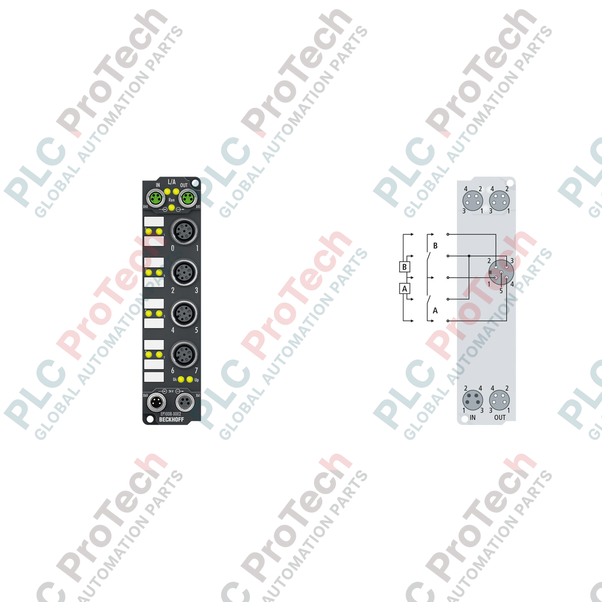
L'architecture matérielle de l'EP1008-0002 est basée sur le protocole EtherCAT à haute vitesse, permettant une acquisition de données synchronisée sur des systèmes distribués à grande échelle. Le module dispose de huit entrées numériques conformes aux normes EN 61131-2 (Type 1/3), utilisant un filtre d'entrée de 3,0 ms pour supprimer efficacement les interférences électriques et éliminer les rebonds des contacts mécaniques. La connexion s'effectue via des connecteurs circulaires M12 5 broches standard de l'industrie, offrant une interface sécurisée et antivibrations pour les capteurs. La distribution d'alimentation est gérée par un système dédié de connexion M8 en entrée et en sortie, permettant un chaînage efficace de plusieurs boîtiers. Le circuit interne est isolé électriquement jusqu'à 500 V, protégeant le segment principal du réseau EtherCAT contre les surtensions côté terrain ou les boucles de masse.
Spécifications techniques
| Attribut |
Détails des spécifications |
| Modèle |
EP1008-0002 |
| Marque |
BECKHOFF |
| Origine |
Allemagne |
| Protocole |
EtherCAT |
| Nombre d'entrées |
8 entrées numériques (Type 1/3) |
| Tension nominale |
24 VCC (-15 % / +20 %) |
| Temps de filtrage d'entrée |
3,0 ms |
| Tension du signal "0" |
-3 à +5 V |
| Tension du signal "1" |
11 à 30 V |
| Consommation de courant |
120 mA depuis US |
| Méthode de connexion |
M12 x 1 (Entrées), M8 (Alimentation/Bus) |
| Matériau du boîtier |
Polyamide PA6 |
| Indice de protection |
IP65, IP66, IP67 |
| Température de fonctionnement |
-25 à +60 °C |
| Poids |
165 g (env.) |
| Dimensions |
30 mm x 126 mm x 26,5 mm |
| Poids d'expédition |
2,0 kg |
FAQ techniques
Comment le EP1008-0002 gère-t-il l'alimentation des capteurs en cas de court-circuit ?
Le module alimente les capteurs à partir de la tension de commande (US). Il est équipé d'une protection contre les courts-circuits pour l'alimentation totale des capteurs, avec une limite de courant maximale de 0,5 A. En cas de défaut au niveau du capteur, le module empêche que ce défaut endommage l'électronique interne ou interrompe la communication EtherCAT principale.
Quelle est la principale différence entre les modules EP1008-0002 et EP1008 standard ?
La variante -0002 utilise spécifiquement des connecteurs d'entrée M12 (5 broches, codage a) au lieu des connecteurs M8 plus petits présents sur les modèles standards. Cela permet l'utilisation de câbles capteurs M12 standard, souvent préférés dans les environnements industriels lourds pour leur durabilité mécanique.
Ce module est-il adapté aux atmosphères explosives ou aux emplacements dangereux ?
Oui, le EP1008-0002 est certifié ATEX avec le marquage Ex II 3 G Ex nA IIC T4 Gc. Cela confirme son aptitude à une utilisation en zone 2 à risque, à condition qu'il soit installé conformément aux exigences spécifiques de sécurité pour les équipements non étincelants.
Guide d'ingénierie et d'installation
-
Blindage et mise à la terre : Pour garantir une immunité maximale aux CEM dans les environnements à forte interférence, utilisez toujours des câbles M8 blindés pour l'interface bus EtherCAT. Les connecteurs à vis doivent être serrés au couple spécifié (généralement 0,4 Nm pour M8 et 0,6 Nm pour M12) pour maintenir l'étanchéité IP67 et assurer un chemin de terre fiable à travers le boîtier du connecteur.
-
Gestion thermique : Bien que le module soit conçu pour fonctionner jusqu'à 60 °C, évitez de monter l'appareil en contact direct avec des machines générant de la chaleur ou dans des poches d'air stagnantes. Le montage vertical est recommandé pour faciliter la convection naturelle. Assurez-vous que la consommation totale de courant pour les 8 capteurs ne dépasse pas la limite de 0,5 A afin d'éviter un déclenchement thermique.
-
Redondance d'alimentation : Lors de la connexion en chaîne d'alimentation via les connecteurs M8 en aval, calculez la chute de tension totale sur la chaîne. Pour les longues distances de câble, vérifiez que la tension terminale au dernier module reste dans la tolérance de 24 VDC (-15 %) afin d'éviter des défaillances intermittentes du signal d'entrée.