Présentation du produit
Le EPI2008-0001 (EPI2008-0001) est une boîte IO-Link industrielle haute performance de Beckhoff, conçue pour faire le lien entre les capteurs/actionneurs de terrain et les systèmes de contrôle de niveau supérieur. Ce module de sortie numérique 8 canaux est conçu pour l'automatisation décentralisée, permettant la connexion directe des actionneurs dans des environnements difficiles sans nécessiter d'armoire de commande protectrice. En utilisant le protocole IO-Link V1.1 (Classe B), le EPI2008-0001 assure des débits de transfert de données élevés de 230,4 kbaud (COM 3) et offre des capacités de diagnostic étendues. Sa construction robuste avec indice de protection IP67 en fait une solution idéale pour la manutention, les lignes d'assemblage automobile et les industries agroalimentaires où la résistance à l'humidité, aux vibrations et à la poussière est une nécessité mécanique pour réduire les temps d'arrêt système et simplifier le câblage sur le terrain.
Configuration technique
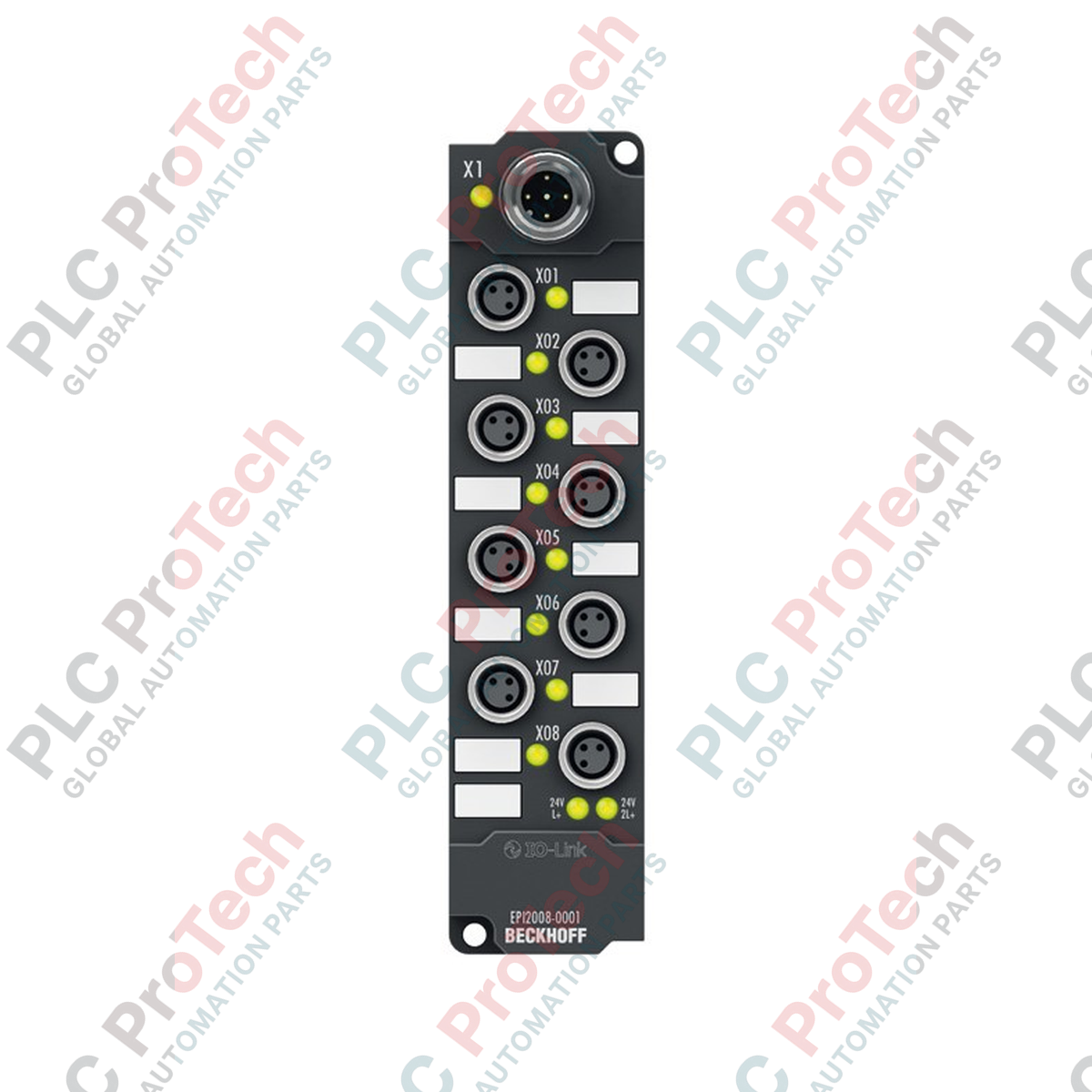
Le EPI2008-0001 présente un design modulaire et compact optimisé pour un montage direct sur machine. Il est équipé d’un connecteur M12 codé A pour la communication IO-Link et l’alimentation, ainsi que de huit connecteurs à vis M8 pour les signaux de sortie. La spécification « Classe B » indique que le module fournit des lignes d’alimentation supplémentaires (P24) pour les actionneurs connectés, électriquement isolées de l’alimentation logique (L+). Chacun des 8 canaux supporte un courant nominal de sortie de 0,5 A et est individuellement protégé contre les courts-circuits, garantissant qu’une défaillance sur un actionneur ne compromet pas l’ensemble du module. La logique interne consomme typiquement 100 mA sur la ligne L+, tandis que la ligne d’alimentation auxiliaire gère le courant de charge, ce qui en fait un choix fiable pour des configurations E/S à haute densité dans des environnements EMC exigeants.
Caractéristiques techniques
| Caractéristique |
Détails de la spécification |
| Modèle |
EPI2008-0001 |
| Marque |
BECKHOFF |
| Communication |
IO-Link V1.1, Classe B |
| Débit de transfert |
230,4 kbaud (COM 3) |
| Nombre de sorties |
8 sorties numériques |
| Connexion (IO-Link) |
1 x connecteur M12, codé A |
| Connexion (Sortie) |
M8, type à vis |
| Tension nominale |
24 V DC (-15 % / +20 %) |
| Courant de sortie max. |
0,5 A par canal |
| Indice de protection |
IP65 / IP66 / IP67 |
| Température de fonctionnement |
-25 à +60 degrés Celsius |
| Poids |
env. 165 g |
FAQ techniques
Quels sont les avantages diagnostiques de l’interface IO-Link V1.1 ?
Le EPI2008-0001 fournit des données de statut en temps réel via le maître IO-Link. Cela inclut la détection de court-circuit spécifique à chaque canal et la surveillance de la tension d’alimentation. Ces paramètres peuvent être lus par l’automate programmable (PLC) pour déclencher des alertes de maintenance prédictive avant une panne totale du système.
Le port « Classe B » signifie-t-il que j’ai besoin d’un maître IO-Link spécial ?
Oui, pour exploiter pleinement les capacités du EPI2008-0001, il doit être connecté à un port maître IO-Link Classe B. Cela garantit que l’alimentation auxiliaire isolée 24 V (P24) est correctement fournie aux actionneurs via les broches supplémentaires du connecteur M12.
Ce module peut-il être monté dans n’importe quelle orientation ?
Le module est conçu pour une position d’installation « variable ». Sa haute résistance aux vibrations (EN 60068-2-6) et aux chocs (EN 60068-2-27) assure une performance constante qu’il soit monté horizontalement sur un cadre de convoyeur ou verticalement sur un bras robotique.
Guide d’ingénierie et d’installation
Séparation de l’alimentation et sécurité :
Le EPI2008-0001 maintient une isolation électrique entre l’électronique de commande (L+) et l’alimentation auxiliaire des sorties (P24). Lors du câblage de votre maître IO-Link, assurez-vous que les deux circuits d’alimentation sont correctement protégés par fusibles. Dans les applications critiques pour la sécurité, l’alimentation P24 peut être coupée extérieurement via un relais de sécurité pour mettre les 8 sorties en « état sûr » sans perdre la communication IO-Link ni les données de diagnostic.
Couple de serrage et étanchéité des connecteurs M8 :
Pour maintenir l’indice de protection IP67, tous les connecteurs à vis M8 doivent être serrés au couple spécifié par le fabricant (généralement 0,4 Nm). Les ports non utilisés doivent être scellés avec des capuchons de protection M8 professionnels. Ne pas sceller les ports inutilisés entraînera une infiltration d’humidité, pouvant provoquer des courts-circuits internes et des dommages permanents à la carte logique.
Bonnes pratiques EMC et mise à la terre :
Bien que le module soit conforme à la norme EN 61000-6-2/4 pour l’immunité EMC, il est essentiel de mettre à la terre la surface de montage si elle est métallique. Si le montage se fait sur des surfaces non conductrices, assurez-vous que la terre fonctionnelle (FE) est connectée via les trous de fixation fournis à un point de mise à la terre central pour détourner les interférences haute fréquence de la ligne de communication IO-Link.