1 de 3

Module de sortie analogique GE Fanuc IC694ALG392 PACSystems RX3i et série 90-30

Module de sortie analogique GE Fanuc IC694ALG392 PACSystems RX3i et série 90-30

Il ne reste que 2 article(s) en stock
  • Fabricant : General Electric

  • N° de produit : IC694ALG392

  • Pays d'origine :États-Unis

  • Type de produit : Module de sortie analogique

  • Code-barres : 8537101190

  • Paiement : Virement bancaire, Western Union

  • Poids : 900g

  • Dimensions : 20 cm x 11,5 cm x 5,7 cm

  • Port d'expédition : Xiamen

  • Garantie : 12 mois

Quantité
Voir les détails complets

Description

The IC694ALG392 is an 8-channel analog output module designed for use with PACSystems RX3i and Series 90-30 PLC systems. It provides up to eight single-ended output channels with current loop outputs and/or voltage outputs. Each output channel can be independently set up using the configuration software for any of these ranges: 0 to +10 V (unipolar), -10 to +10 V (bipolar), 0 to 20 mA, and 4 to 20 mA.

Each channel of the IC694ALG392 is capable of converting 15 to 16 bits (depending on the range selected) of binary data to an analog output. All eight channels are updated approximately every 8 milliseconds, determined by the I/O scan time and application. In current modes, the module reports an Open Wire fault to the CPU for each channel. As long as external power is applied to the module, each output will maintain its last value or reset to zero, as configured, when system power is interrupted. This module can be installed in any I/O slot of an RX3i or Series 90-30 system.

Features

  • 1 to 8 selectable single-ended analog output channels.
  • Flexible software configuration for multiple current and voltage ranges.
  • High-resolution conversion (15 to 16 bits depending on the selected range).
  • Fast update rate of approximately 8 milliseconds for all eight channels.
  • Channel-specific Open Wire fault reporting to the CPU in current loop modes.
  • Configurable default behavior (maintain last value or reset to zero) upon system power interruption.
  • Dual LED diagnostics driven by the backplane power bus to indicate module state and user supply status.

Applications

  • Proportional control valves and industrial actuators.
  • Speed reference signaling for variable frequency drives (VFD).
  • Dynamic chart recorders and process data logging equipment.
  • Interface connections to remote instrumentation panels.
  • Industrial automated processes in standard and Class I, Division 2 environments.

Ordering Information

Model / Version Description
IC694ALG392-AA Initial product release for RX3i module series (Version 1.00).
IC694ALG392-BB RX3i module series revision; not compatible with a Series 90-30 Hand-held Programmer.
IC694ALG392-BC RX3i module series firmware version 1.01 release.
IC694ALG392-CD RX3i module series firmware version 1.60 release.
IC693ALG392-A Initial release for Series 90-30 module series (Version 1.00).
IC693ALG392-B Series 90-30 module series with CE certification (Version 1.00).
IC693ALG392-C Series 90-30 module series with ATEX approval for Group 2, category 3 applications (Version 1.00).
IC693ALG392-BD Series 90-30 module series with updated processor and D/A converter (Version 1.00).
IC693ALG392-BE Series 90-30 module series firmware version 1.01 release.
IC693ALG392-CF Series 90-30 module series firmware version 1.60 release.

Technical Specifications

Parameter Specification
Manufacturer GE Intelligent Platforms, Inc. 
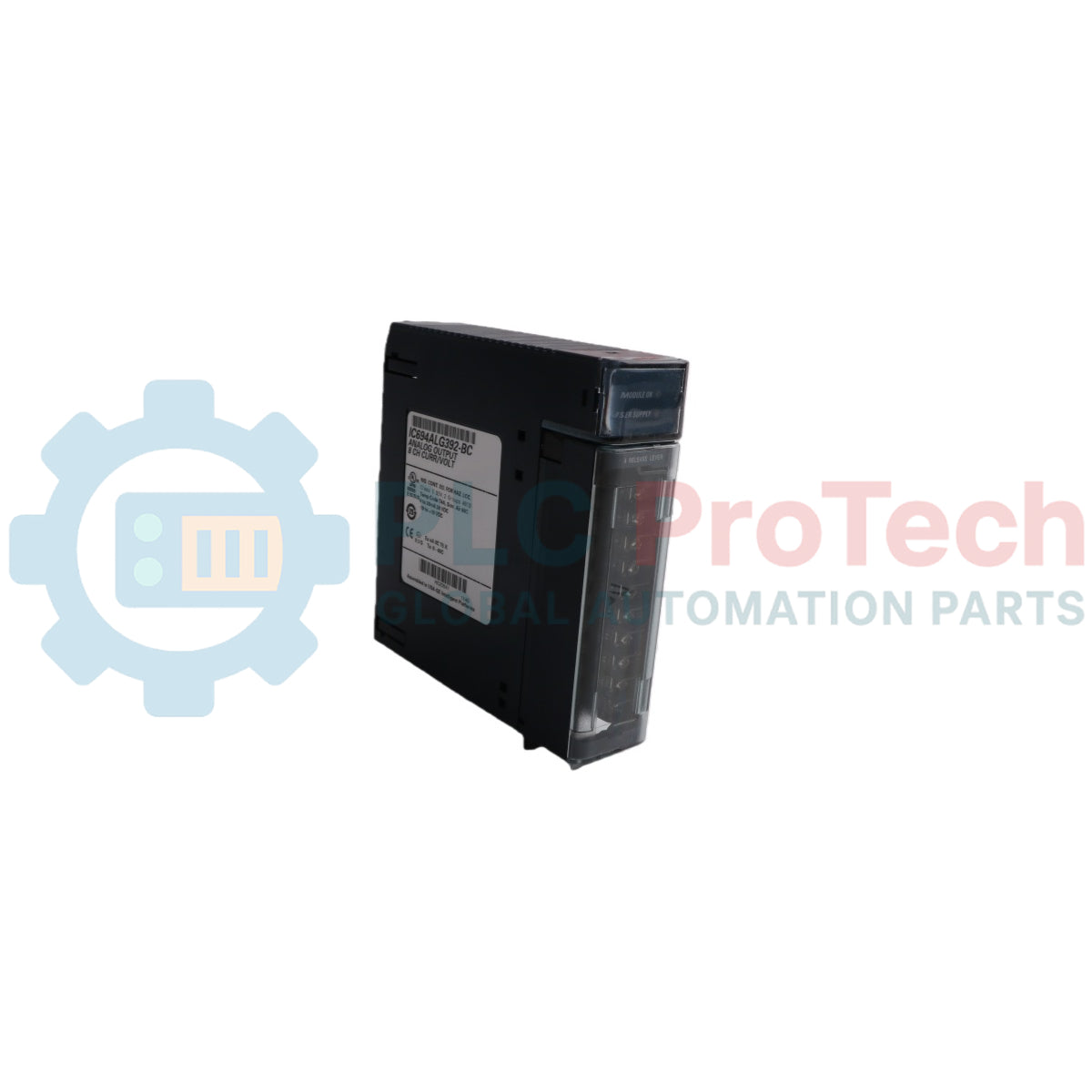
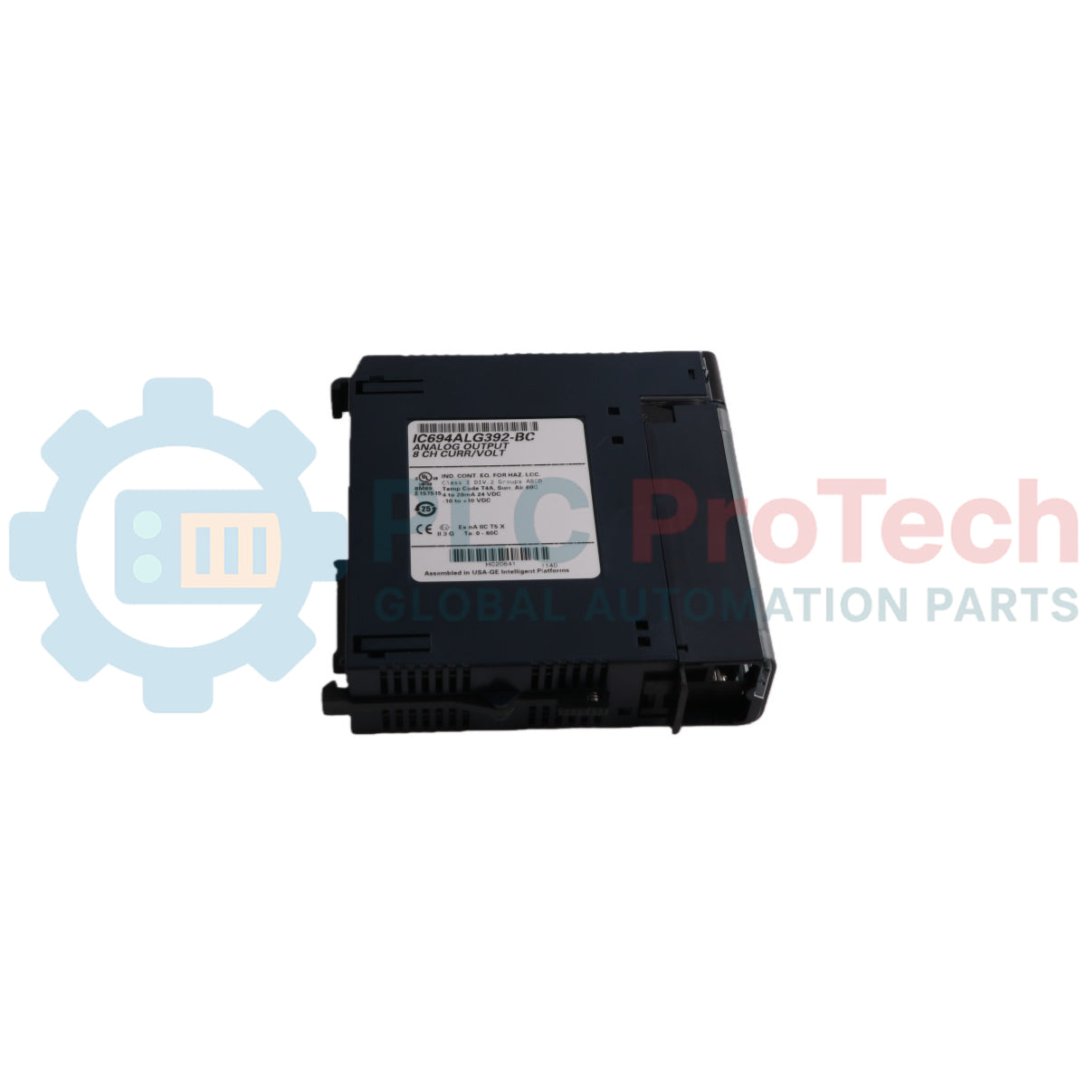
Model IC694ALG392 
Number of Output Channels 1 to 8 selectable, single-ended 
Output Current Range 4 to 20 mA and 0 to 20 mA 
Output Voltage Range 0 to 10 V and -10 V to +10 V 
Calibration Factory calibrated to 0.625 uA for 0 to 20 mA; 0.5 uA for 4 to 20 mA; and 0.3125 mV for voltage (per count) 
Resolution (4 to 20 mA) 0.5 uA (1 LSB = 0.5 uA) 
Resolution (0 to 20 mA) 0.625 uA (1 LSB = 0.625 uA) 
Resolution (0 to 10 V) 0.3125 mV (1 LSB = 0.3125 mV) 
Resolution (-10 to +10 V) 0.3125 mV (1 LSB = 0.3125 mV) 
Update Rate 8 milliseconds (approximate, all eight channels). Determined by I/O scan time, application dependent. 
Absolute Accuracy (Current Mode) +/-0.1% of full scale @ 25 degC (77 degF), typical; +/-0.25% of full scale @ 25 degC (77 degF), maximum; +/-0.5% of full scale over operating temperature range (maximum) 
Absolute Accuracy (Voltage Mode) +/-0.25% of full scale @ 25 degC (77 degF), typical; +/-0.5% of full scale @ 25 degC (77 degF), maximum; +/-1.0% of full scale over operating temperature range (maximum) 
User Supply Voltage (Nominal) +24 VDC, from user supplied voltage source 
External Supply Voltage Range 20 VDC to 30 VDC 
Power Supply Rejection Ratio (Current) 5 uA/V (typical), 10 uA/V (maximum) 
Power Supply Rejection Ratio (Voltage) 25 mV/V (typical), 50 mV/V (maximum) 
External Power Supply Voltage Ripple 10% (maximum) 
Internal Supply Voltage +5 VDC from PLC backplane 
Maximum Compliance Voltage VUSER -3 V (minimum) to VUSER (maximum) 
User Load (Current Mode) 10 to 850 Ohms (minimum at VUSER = 20 V, maximum 1350 Ohms at VUSER = 30 V). (Load less than 800 Ohms is temperature dependent.) 
Output Load Capacitance (Current Mode) 2000 pF (maximum) 
Output Load Inductance (Current Mode) 1 H 
Output Loading (Voltage Mode) 5 mA (2 K Ohms minimum resistance) 
Output Load Capacitance (Voltage Mode) 1 uF maximum capacitance 
Isolation, Field to Backplane 250 VAC continuous; 1500 VDC for 1 minute (optical and to frame ground) 
Power Consumption (Internal) 110 mA from +5 VDC PLC backplane supply 
Power Consumption (External) 315 mA from +24 VDC user supply 

Connections and Interfaces

Terminal Signal Definition
1 User Supplied +24 VDC Input 
2 Channel 1 Voltage Output 
3 Channel 1 Current Output 
4 Channel 2 Voltage Output 
5 Channel 2 Current output 
6 Channel 3 Voltage Output 
7 Channel 3 Current output 
8 Channel 4 Voltage Output 
9 Channel 4 Current output 
10 Channel 5 Voltage Output 
11 Channel 5 Current output 
12 Channel 6 Voltage Output 
13 Channel 6 Current output 
14 Channel 7 Voltage Output 
15 Channel 7 Current output 
16 Channel 8 Voltage Output 
17 Channel 8 Current output 
18 Voltage Common 
19 Current Common/User +24 VDC Return 
20 Frame ground connection for cable shields 


Note: Each channel can be configured to operate as a voltage output or a current output - not both simultaneously.

Module Status Indicators

LED State Indicates
OK ON Module OK and configured 
OK Flashing Module OK but not configured 
OK OFF Module is defective or no +5V backplane power present 
USER OK ON External power supply present 
USER OK OFF No user power 

Installation Guidelines

  • External Power Connection: The module must receive its 24 VDC power from an external source connected directly to Terminal 1 and Terminal 19 of the module's terminal block.
  • Thermal Derating: For maximum performance and module life, the module should be operated at maximum load resistance to offload heat. Module thermal deratings depend on the voltage level and the mix of current and voltage outputs. For example, at VUSER = 30 V with 2 voltage channels (2 K Ohm loads) and 3 current channels (shorted loads), the maximum operating temperature is approximately 52.5 degC.
  • RF Susceptibility and Shielding: In order to meet the specified RF susceptibility levels, the system must be mounted in a metal enclosure when this module is present. In the presence of severe RF interference, accuracy may be degraded to +/-1% full scale (FS) for current outputs and +/-3% FS for voltage outputs.
  • Cable Grounding: Wire the cable shield ground directly to Terminal 20 (Frame Ground).
  • Hazardous Area Precautions: Suitable for use in Class I, Division 2, Groups A, B, C, and D or non-hazardous locations only.
  • Explosion Hazard Warnings: Turn off power before replacing or wiring modules when in hazardous locations. Do not disconnect equipment unless power has been switched off or the area is known to be non-hazardous. Component substitution may impair suitability for Class I, Division 

System Compatibility Requirements

  • Series 90-30 CPU Firmware: For Series 90-30 PLC CPU firmware versions 3.3 to 4.6, the module must be configured for 16 %I inputs, otherwise a Loss of Module Fault will occur. CPU firmware must be version 5.0 or later to configure the module for 8 %I inputs.
  • Hand-Held Programmer: Only Series 90-30 modules version C or earlier support the Series 90-30 Hand-held Programmer. Series 90-30 modules version BD or later and all versions of RX3i modules cannot be used with a Hand-held Programmer.

Compliance and Certifications

  • Class I, Division 2, Groups A, B, C, D Hazardous Locations 

Product Documentation

Technical Datasheet (PDF) Complete specifications and technical drawings.
Download Now

Un seul canal peut-il fournir simultanément une tension et un courant ?

Non. Chacun des huit canaux doit être configuré via le logiciel pour fonctionner soit en sortie de tension, soit en sortie de courant, mais ne peut pas fournir les deux en même temps.

Que se passe-t-il avec les sorties analogiques si le châssis du PLC perd son alimentation ?

Si l'alimentation système est coupée mais que le +24 VCC externe reste appliqué au bornier, chaque canal conservera sa dernière valeur commandée ou se réinitialisera à zéro selon sa configuration.

Comment le module signale-t-il une défaillance du câblage de terrain au système de contrôle ?

Lorsqu'il fonctionne en modes courant (0 à 20 mA ou 4 à 20 mA), le module surveille automatiquement le circuit et enregistre une faute de fil coupé directement dans le CPU si une boucle est interrompue.

Pourquoi le module doit-il être installé dans un boîtier métallique ?

Un boîtier métallique est nécessaire pour respecter les normes de susceptibilité aux radiofréquences et éviter la dégradation de la précision causée par des interférences électromagnétiques ou radiofréquences sévères.

Expédition express mondiale

  • Livraison standard : 4 à 6 jours ouvrables via DHL, FedEx et UPS.
  • Expédition express : Expédition le jour même pour les commandes en stock passées avant 14h00 (GMT+8).
  • Couverture mondiale : Service dans plus de 150 pays, avec livraison rapide en Arabie Saoudite et aux Émirats arabes unis.

Retours et garantie

  • Garantie de 30 jours : Retours acceptés pour les produits en stock dans leur emballage d’origine scellé en usine.
  • Garantie de 12 mois : Chaque composant industriel est couvert par notre garantie technique professionnelle.

Les commandes sont traitées et livrées du lundi au vendredi (hors jours fériés).


Pour connaître les conditions d’éligibilité complètes, les frais de restockage et les détails des retours internationaux, veuillez consulter notre site officiel Politique de remboursement et de retour .

TECHNICAL SPECIFICATIONS

Color pattern
Noir
Country of origin
États-Unis
Power source
Alimentation DC

Produits récemment consultés

Connaissances techniques

Guide des préhenseurs robotiques : de la manipulation délicate à l'automatisation lourde

Les pinces robotiques modernes évoluent au-delà des mâchoires mécaniques traditionnelles. Des systèmes adhésifs inspirés du gecko et des pinces souples de qualité alimentaire aux outils d'entrepôt...

Retour en arrière : comment les premiers moteurs électriques ont transformé l'exploitation minière souterraine

Des compresseurs à courant continu entraînés par corde aux wagonnets de mine alimentés par batterie, les premières opérations minières ont marqué un tournant dans l’électrification industrielle. Cet...

Factory I/O : un outil moderne de simulation PLC pour la formation à l'automatisation industrielle

Factory I/O révolutionne l'enseignement des automates programmables industriels (API) en proposant des simulations industrielles 3D immersives pour les étudiants, les ingénieurs et les équipes de...

Programmation des cycles de mouvement à axe unique sur un servo-variateur CMZ

Ce tutoriel examine comment la fonctionnalité PLC intégrée dans un servo-variateur CMZ SBD peut exécuter des programmes de mouvement autonomes, y compris la logique de référencement, le contrôle de...

Configuration de contrôle de mouvement à axe unique avec les servomoteurs CMZ

Ce tutoriel explore la mise en service d'un système de mouvement servo à un seul axe utilisant un variateur CMZ SBD, couvrant l'installation matérielle, la mise à l'échelle de l'axe, la configuration...

Intégration du PLC Mitsubishi FX avec le variateur FR-D700 et le contrôle HMI

Ce tutoriel explique comment les automates programmables Mitsubishi FX s'intègrent avec les variateurs de fréquence FR-D700 et les panneaux HMI pour le contrôle avant/arrière des moteurs. Il couvre...