| Tension nominale d'entrée |
120/240 VAC, ou 125 VDC |
| Plage de tension d'entrée (source AC) |
Plage de tension d'entrée (source AC) de 90 à 264 VAC, 47 à 63 Hz |
| Plage de tension d'entrée (source DC) |
Plage d'entrée continue de 100 à 150 VDC |
| Consommation électrique d'entrée |
Consommation électrique typique de 135 watts, enveloppe de charge maximale de 160 watts |
| Courant d'appel de crête à la moitié du cycle d'entrée |
Limite continue typique de 3 ampères |
| Facteur de puissance actif |
Facteur de puissance actif supérieur à 0,93 en charge opérationnelle complète continue |
| Capacité de puissance de sortie |
100 watts maximum total combiné sur les 3 voies de sortie |
| Tension de sortie (rail +5 VDC) |
4,90 à 5,25 volts (référence nominale 5,07 volts) |
| Tension de sortie (rail +12 VDC) |
11,75 à 12,6 volts |
| Tension de sortie (rail -12 VDC) |
-12,6 à -11,75 volts |
| Limite de surtension (+5 VDC sortie) |
Fenêtre de coupure de surtension de 5,7 à 6,7 volts |
| Limite de surintensité (+5V sortie) |
Seuil de protection typique de 21 ampères |
| Limite de surintensité (+12V sortie) |
Seuil de protection typique de 3,5 ampères |
| Limite de surintensité (-12V sortie) |
Seuil de protection typique de 1,6 ampères |
| Capacité de maintien de tension |
21 millisecondes minimum maintenues à partir du point de perte de l'entrée AC |
| Plage de température de fonctionnement |
0 à 60 degrés Celsius (32 à 140 Fahrenheit) ambiant |
| Plage de température de stockage |
-40 à +85 degrés Celsius (-40 à +185 Fahrenheit) ambiant |
| Classement et type de fusible interne |
Fusible de sécurité haute capacité 2 ampères, 250 volts |
| Couple de serrage des vis du bornier |
12 in-lb (1,3 N-m) |
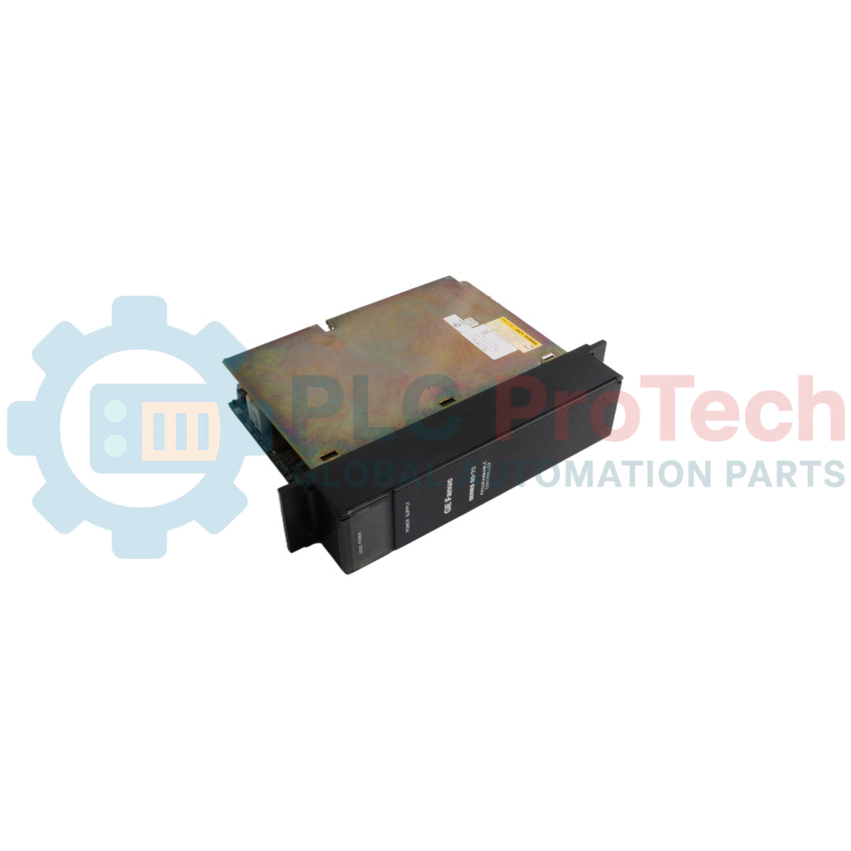
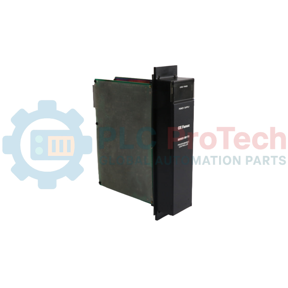
| Fabricant |
GE Fanuc Automation |
| Pays d'origine |
USA |
| Poids d'expédition (calculé) |
1,95 kg |
| Dimensions du boîtier (calculées) |
280 mm x 220 mm x 85 mm |