Profil du système et intégrité opérationnelle
La DS215TCEAG1BZZ01A agit comme la barrière de protection définitive au niveau matériel dans l'architecture de contrôle de turbine Speedtronic Mark V de General Electric. Installé directement dans le noyau de protection dédié (désigné comme le noyau), ce module critique pour la sécurité exécute des diagnostics en temps réel sur les conditions d'urgence de survitesse et les métriques critiques de surveillance de flamme. Les centrales thermiques de base, les grandes raffineries pétrochimiques et les installations d'entraînement mécanique isolées déploient la DS215TCEAG1BZZ01A (DS215TCEAG1BZZ01A) pour gérer les boucles de déclenchement d'urgence indépendamment des processeurs de contrôle principaux. En traitant les impulsions brutes des capteurs de vitesse et en calculant les marges de déclenchement via une logique matérielle embarquée dédiée, cette carte agit instantanément lors des conditions de turbine en fuite pour décharger les têtes de déclenchement hydraulique. Cette réaction en moins d'une milliseconde évite les contraintes mécaniques catastrophiques, prévient les dommages critiques à l'arbre et préserve l'infrastructure de l'usine tout en réduisant les arrêts de maintenance à long terme.
Topographie matérielle et routage du noyau
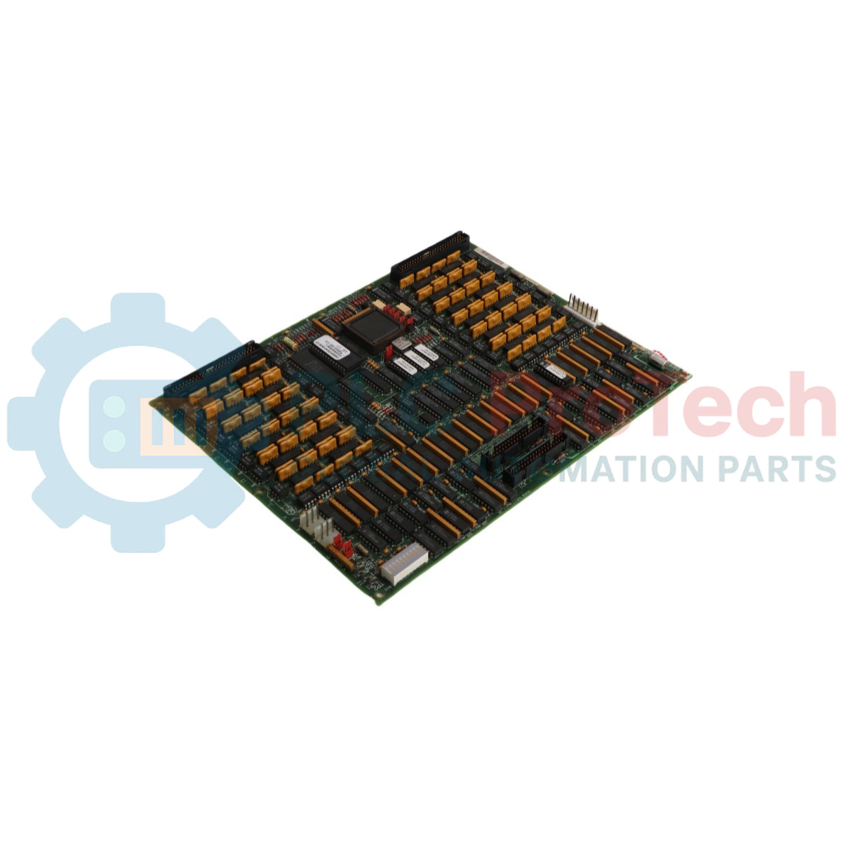
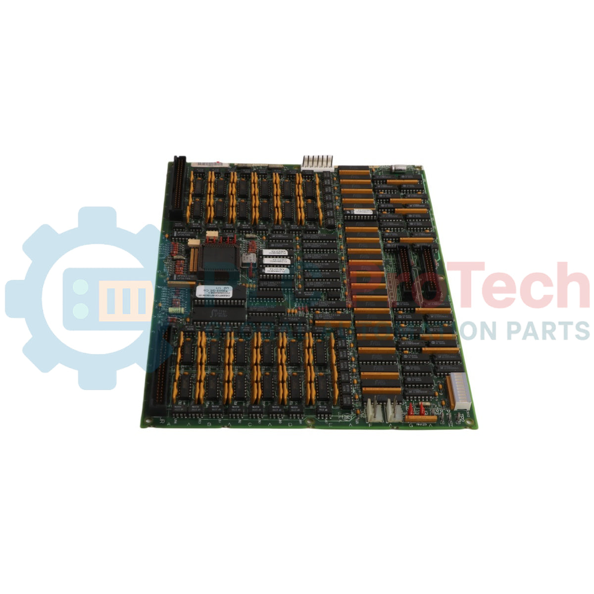
L'architecture structurelle de la DS215TCEAG1BZZ01A tire parti de blocs de traitement indépendants et de nœuds d'interface à haute densité.
-
Processeur de protection isolé : Héberge un microprocesseur embarqué haute performance exécutant des routines de sécurité déterministes alimentées par un firmware stocké dans des blocs de mémoire EPROM effaçables et amovibles.
-
Alimentation haute tension du capteur de flamme : Intègre un circuit haute tension spécialisé via le connecteur JW capable de distribuer jusqu'à 335 VCC pour alimenter des réseaux externes de suivi de flamme sur le terrain.
-
Programmation matérielle multipoint : Dispose d'une matrice de 30 cavaliers matériels physiques Berg pour coder manuellement la position exacte du slot opérationnel et la logique de vote dans le noyau.
-
Communications à double bus : Intègre des prises de connexion IONET en chaîne JX1 et JX2 pour transmettre les résultats de diagnostic en arrière-plan et les données d'état de déclenchement via des liaisons de communication à haute fiabilité.
Spécifications et paramètres du système
| Métrique d'ingénierie |
Classement technique |
| Numéro de modèle |
DS215TCEAG1BZZ01A (interchangeable avec DS200TCEAG1BZZ01A) |
| Fabricant de la marque |
General Electric (cartes GE & contrôle de turbine) |
| Série de contrôle |
Speedtronic Mark V (série DS200) |
| Acronyme fonctionnel |
Carte TCEA |
| Zone de montage du noyau |
Noyau (module d'interface de protection) |
| Unité de traitement embarquée |
Microprocesseur dédié unique à haute vitesse |
| Stockage des instructions |
Modules EPROM amovibles préprogrammés en usine |
| Protection embarquée |
3 fusibles haute capacité |
| Configuration matérielle en matrice |
30 blocs de cavaliers Berg individuels |
| Sortie du moniteur de flamme |
Sortie 335 VCC via connecteur JW |
| Communication inter-modules |
Connecteurs IONET JX1 et JX2 en guirlande |
| Lien porteur de signal |
Connecteur JK (interface avec la carte TCEB) |
| Lien d’action de déclenchement |
Connecteur de sortie JL |
| Protection sous-surface |
Revêtement conforme standard pour PCB |
| Plage de température de fonctionnement |
0 à 60 °C |
| Pays d’origine |
États-Unis |
FAQ sur le diagnostic de boucle de sécurité
Quel rôle spécifique joue le DS215TCEAG1BZZ01A lors d’une phase d’allumage, et comment s’interface-t-il avec le suivi de flamme ?
La carte régule et délivre une tension de polarisation continue de 335 VCC via le connecteur JW aux détecteurs de flamme montés sur le terrain. Elle lit les signaux de faible niveau d’ionisation de flamme retournés, traite l’état d’allumage et fournit une logique de déclenchement d’urgence immédiate en cas d’extinction de flamme pendant le fonctionnement critique de la turbine.
Comment une carte de remplacement reconnaît-elle sa position assignée dans le noyau de protection ?
La position matérielle et les variables d’application sont déterminées par la configuration des 30 cavaliers berg embarqués. Lors de la préparation d’une nouvelle carte, les ingénieurs doivent physiquement reproduire le motif de ces cavaliers sur la carte d’origine pour garantir une interface correcte avec la logique centrale.
Quel est le protocole correct de remplacement si les données EPROM embarquées sont corrompues ?
En cas de défauts du firmware, les EPROM existants peuvent être retirés de leurs sockets et remplacés par des modules de firmware neufs et vérifiés en usine. Comme ces puces sont très sensibles aux décharges électrostatiques, cette procédure doit toujours être réalisée sous protocoles complets de mise à la terre ESD pour protéger les mémoires internes.
Protocole d’ingénierie et d’installation sur site
-
Contrôles de dissipation statique pour la protection des EPROM :
Les modules EPROM embarqués et la logique microprocesseur sont vulnérables aux dommages permanents dus aux décharges électrostatiques. Les techniciens sur site doivent porter un bracelet antistatique relié à la terre avant de déballer ou de toucher la carte. Assurez-vous que la pince de mise à la terre est solidement connectée à une structure métallique mise à la terre et non peinte ou à un établi pour fournir un chemin clair de décharge statique loin des composants.
-
Inspection et remplacement des fusibles de surintensité :
La carte contient 3 fusibles de protection dédiés pour isoler les sous-circuits internes des courts-circuits du câblage externe. Avant la mise en service d’une carte neuve ou réparée, vérifiez la continuité et les valeurs nominales des fusibles. Si un fusible est grillé, dépannez le circuit de flamme 335 VCC externe ou le connecteur de distribution d’alimentation J7 avant de redémarrer le système.
-
Directives de terminaison en guirlande pour IONET :
Lors du raccordement des connecteurs IONET JX1 et JX2 à travers plusieurs modules dans la baie, assurez-vous que les résistances de terminaison à la fin du bus de données sont correctement placées. Des chaînes en guirlande mal fermées créent des réflexions de signal haute fréquence sur le réseau IONET, ce qui peut entraîner des délais d'attente de communication entre le module de protection et le contrôleur maître principal.