Présentation du produit
La IS215REBFH1BA est une carte de circuit imprimé (PCB) spécialisée et à haute fiabilité, développée par GE Energy pour les plateformes de contrôle Mark VIe et Mark VIeS. Fonctionnant comme une passerelle critique de communication et de diagnostic, ce module sert de lien matériel principal entre le contrôleur principal et les circuits de ponts électroniques de puissance utilisés dans les convertisseurs d’éoliennes et les onduleurs photovoltaïques solaires. Les installations industrielles d’énergie verte — y compris les parcs éoliens terrestres et offshore à grande échelle ainsi que les réseaux solaires commerciaux à haute capacité — s’appuient sur la IS215REBFH1BA pour réguler les boucles de modulation rapide de puissance. En facilitant l’acquisition de données en temps réel depuis le pont de puissance et en gérant les commandes de commutation à haute vitesse, cette carte aide à optimiser l’injection de puissance réactive et la stabilisation de la tension. Ce suivi dédié minimise les défauts du réseau, protège les assemblages sensibles d’IGBT contre les surtensions de courant et réduit les temps d’arrêt non programmés des équipements.
Topographie du circuit et architecture d’interface
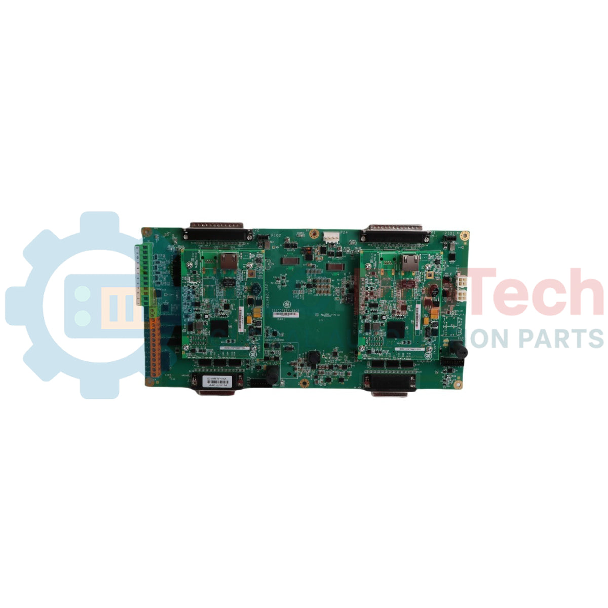
La disposition de la carte, les réseaux de transceivers à haute vitesse et les canaux de diagnostic localisés du substrat d’interface IS215REBFH1BA maintiennent une coordination stricte du contrôle des ponts haute puissance.
-
Lignes de communication par fibre optique : Dispose de ports fibre optique à haute vitesse conçus pour transférer les commandes numériques de commutation et les diagnostics du pont, isolant le contrôleur des interférences électriques haute tension.
-
Conditionneurs de diagnostic du pont : Équipée de circuits analogiques spécialisés qui surveillent les températures du pont, les courants de phase et les mesures de tension du bus DC.
-
Intégration réseau IONet : Communique directement avec le contrôleur maître via le protocole Ethernet propriétaire IONet de GE, permettant une synchronisation déterministe entre les ponts de puissance parallèles.
-
Cœur logique embarqué : Intègre des FPGA (circuits logiques programmables sur le terrain) locaux pour décoder les matrices de contrôle à haute vitesse et gérer les actions de déclenchement immédiates en cas de détection d’un défaut local sur le pont.
Normes de performance technique et limites de fonctionnement
| Paramètre |
Norme de spécification certifiée |
| Identité du modèle |
IS215REBFH1BA |
| Fabricant |
GE Energy (GE Vernova / Contrôle Turbine) |
| Ligne de système de contrôle |
Plateforme d’automatisation Mark VIe / Mark VIeS |
| Classification du module |
REBF - Interface de pont d’énergie renouvelable PCB |
| Révision matérielle |
Variante suffixe fonctionnel H1BA |
| Interface réseau |
Transceivers fibre optique / liens IONet dédiés |
| Protection par revêtement |
Revêtement conforme industriel pour résistance à l’humidité et au sel |
| Alimentation nominale de fonctionnement |
Alimentation de contrôle 24 VDC via connexions du backplane système |
| Plage de température de fonctionnement |
Paramètres de température ambiante de la plaque de base de 0 à 60 °C |
| Limites de température de stockage |
Limites structurelles maximales de -40 à +85 °C |
| Origine de fabrication |
États-Unis (USA) |
FAQ sur le contrôle et le diagnostic des énergies renouvelables
Quelle est la fonction principale de la IS215REBFH1BA dans les enceintes de convertisseurs éoliens ?
La carte agit comme interface à haute vitesse entre le contrôleur principal Mark VIe de la turbine et le pont de puissance refroidi par liquide. Elle traite les signaux de commande de grille en temps réel pour les semi-conducteurs de puissance de l’onduleur tout en collectant les retours de température et de tension afin d’assurer une synchronisation propre avec le réseau électrique.
Comment l’isolation par fibre optique améliore-t-elle la sécurité matérielle sur cette carte ?
En utilisant des liaisons fibre optique pour envoyer et recevoir les commandes de commutation, la carte isole les circuits de contrôle basse tension des composants haute tension de l’onduleur de puissance. Cette séparation physique empêche les surtensions dangereuses ou les transitoires de boucle de masse de revenir endommager les racks du contrôleur principal.
Que signifie le code de révision H1BA concernant les remplacements sur le terrain ?
La désignation H1BA indique la configuration matérielle spécifique et la disposition des composants pour cette variante REBF. Lors du remplacement d’une carte défectueuse dans un panneau de convertisseur en fonctionnement, les techniciens doivent correspondre exactement à ce suffixe pour garantir la compatibilité avec le firmware d’usine existant et les connecteurs.
Guide d’ingénierie terrain et d’installation
-
Gestion des câbles fibre optique et rayons de courbure minimum :
Lors de la connexion des fibres optiques aux ports IS215REBFH1BA, inspectez les embouts des câbles pour vous assurer qu’ils sont exempts de poussière, de graisse ou de condensation. Nettoyez les embouts avec des lingettes spéciales pour fibre optique si nécessaire. Évitez de tordre ou de tirer sur les câbles et maintenez un rayon de courbure supérieur au minimum autorisé pour l’assemblage fibre. Les courbures trop serrées peuvent plier le cœur en verre interne, provoquant une perte de signal et des coupures intermittentes de communication sur le réseau maître.
-
Protocoles de mise à la terre antistatique pour les panneaux d’onduleurs :
Les FPGA et les composants transceivers de ce module sont très sensibles aux décharges électrostatiques (ESD). Les ingénieurs terrain doivent porter un bracelet antistatique correctement relié au châssis de l’enceinte avant de retirer la carte de son emballage anti-statique. Manipulez le module uniquement par ses bords en fibre de verre ou ses entretoises mécaniques pour éviter de toucher les pistes exposées.
-
Contrôles environnementaux pour les enceintes extérieures :
Les panneaux de contrôle d’énergie renouvelable sont souvent situés dans des zones isolées soumises à une forte humidité, à la chaleur ambiante ou aux embruns salins. Bien que la carte soit protégée par un revêtement conforme, les techniciens doivent s’assurer que les ventilateurs de refroidissement, échangeurs de chaleur ou systèmes de climatisation du coffret fonctionnent correctement. Maintenez la température ambiante à l’intérieur du panneau dans la plage certifiée de 0 à 60 °C pour éviter toute dégradation thermique.