Présentation du produit
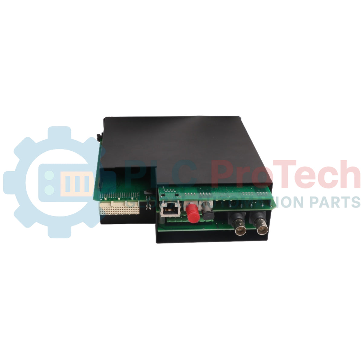
Le UR-8GH (UR8GH) est une interface d’acquisition de données analogiques haute précision conçue par General Electric pour l’écosystème de protection réseau de la série UR (Relais Universels). Fonctionnant comme un bloc de mise à l’échelle primaire à haute densité, cette carte critique réduit en toute sécurité les dynamiques de tension et de courant à haute capacité provenant des transformateurs d’instruments de terrain en lignes de traitement en millivolts pour le cœur arithmétique du relais. Les infrastructures de distribution d’énergie — y compris les postes de commutation à très haute tension, les stations hydroélectriques automatisées et les installations lourdes de traitement pétrochimique — dépendent du UR-8GH (UR8GH) pour capturer les perturbations de ligne sous-cycle et les fluctuations de phase de tension. En fournissant 4 canaux d’entrée galvanique isolés TC (Transformateur de Courant) et 4 TV (Transformateur de Tension) sur un seul substrat, ce module assure des mesures précises en temps réel des lignes, raccourcit les profils de réponse des disjoncteurs lors de défauts de ligne à fort courant et minimise les arrêts non programmés de l’usine.
Configuration technique et interface des capteurs
La matrice de câblage structurelle avancée, les filtres de séparation des canaux et les limites de fréquence opérationnelle du module de mesure UR-8GH gèrent la précision de sa surveillance du réseau.
-
Ingestion de paramètres à double source : Dispose d’une configuration équilibrée de grille avec 4 canaux TC et 4 canaux TV conçue pour suivre simultanément les lignes de tension et de courant triphasées ainsi qu’un chemin de terre neutre indépendant.
-
Limites de protection galvanique : Met en œuvre une barrière d’isolation structurelle avancée entre le bloc de connexion terminale et le backplane de traitement interne, empêchant les pics de défaut inductifs sévères d’endommager le processeur central CPU.
-
Synchronisation de phase sous-échantillonnage : Fonctionne en parfaite synchronisation avec la logique du backplane du relais universel, garantissant une absence totale de décalage d’angle de phase entre les échantillonnages correspondants des formes d’onde de courant et de tension.
-
Matrice dynamique de cartographie du réseau : Transmet des valeurs analogiques haute fidélité au micrologiciel du système hôte pour supporter des chemins logiques de protection complexes, incluant la protection de distance (21), la surintensité directionnelle (67) et la télémétrie de surveillance synchronisée des lignes.
Spécifications techniques
| Métrique de protection |
Norme de spécification du système d'usine |
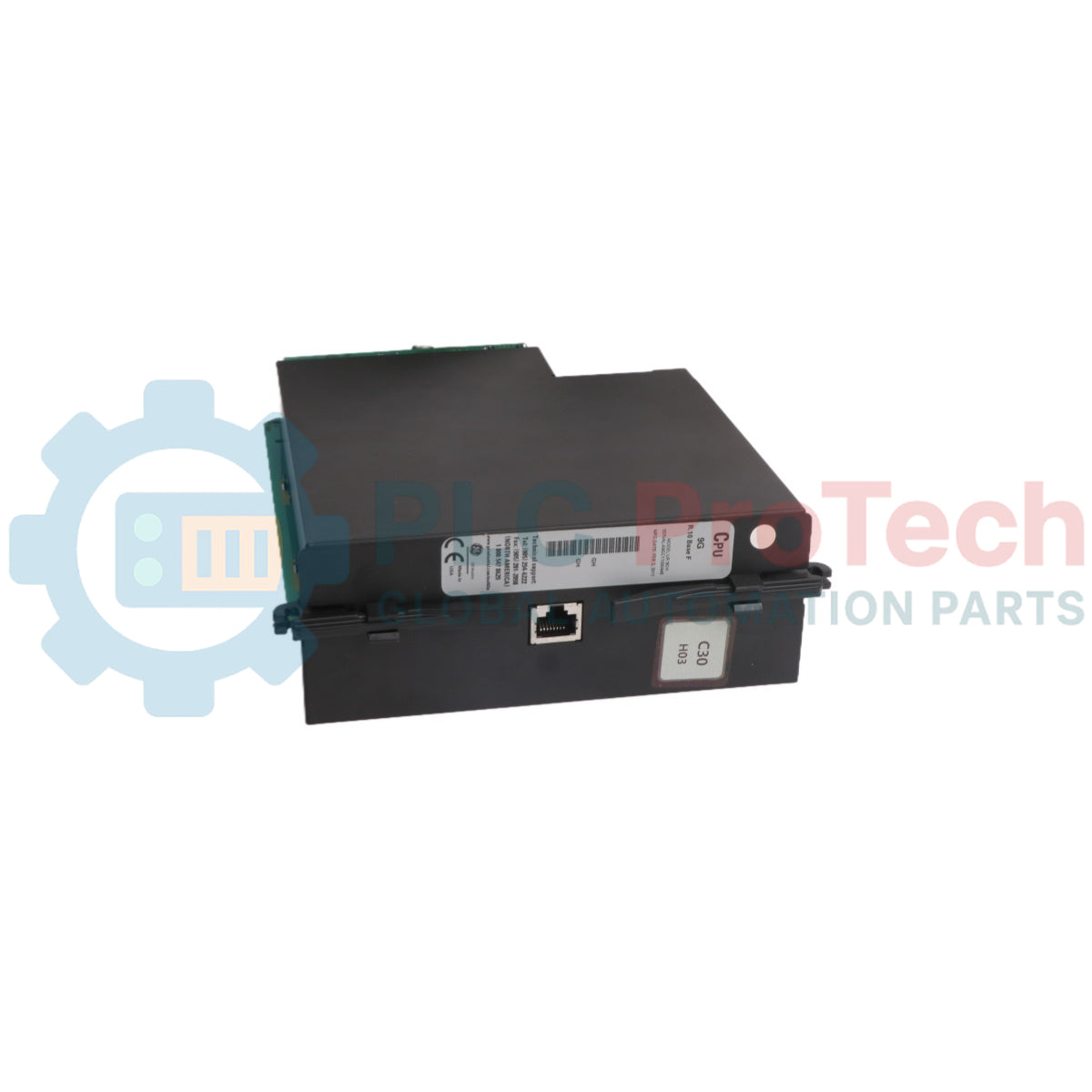
| Désignation du modèle |
UR-8GH |
| Fabricant de la marque |
GE Multilin (General Electric Grid Solutions) |
| Ligne du système de contrôle |
Plateforme des relais universels série UR |
| Classification du module |
Module d'entrée analogique standard 4 CT / 4 VT |
| Entrées de courant (CT) |
4 canaux isolés avec limites thermiques continues élevées |
| Entrées de tension (VT) |
4 canaux isolés optimisés pour lignes d'instrumentation |
| Limites de suivi de fréquence |
Compatibilité réseau nominale 50 Hz / 60 Hz |
| Résolution du journal de données |
Matrice analogique-numérique multi-échantillonnage à haute vitesse |
| Logiciel de configuration |
Plateforme utilitaire de configuration EnerVista UR |
| Dimensions physiques |
Boîtier standard pour emplacement d'extension UR (environ 15 cm x 18 cm x 4 cm) |
| Poids d'expédition matériel |
1,35 kg |
| Plage de température de fonctionnement |
-40 à +60 °C Plage environnementale continue |
| Lieu de fabrication |
Markham, Ontario, Canada |
FAQ sur les systèmes de protection et de diagnostic
Comment les ingénieurs système vérifient-ils l'étalonnage individuel CT/VT ou dépannent-ils les métriques de circuit ouvert sur l'UR-8GH ?
Les mesures vectorielles analogiques en direct peuvent être évaluées passivement via le panneau LCD avant du châssis Universal Relay ou diagnostiquées directement via l'espace de travail du logiciel EnerVista UR. Cet environnement de programmation affiche en temps réel des graphiques de magnitude de courant, d'angles de phase et de distorsions harmoniques, permettant un diagnostic immédiat des inversions de phase du transformateur de courant ou des lignes neutres non mises à la terre.
Quelles sont les conséquences d'une faute de circuit ouvert non programmée traversant un canal actif de transformateur de courant UR-8GH ?
Une condition de circuit ouvert sur une boucle secondaire CT active génère des transitoires haute tension dangereux aux bornes du bloc de connexion, présentant un risque de choc mortel pour le personnel et provoquant une défaillance diélectrique dans le circuit d'entrée du module. Les techniciens doivent s'assurer que les blocs de court-circuit sont bien engagés avant de déconnecter toute vis de borne de ligne de courant.
Le module UR-8GH peut-il être échangé ou inséré pendant que le panneau d'automatisation du réseau est sous tension ?
Non. Pour éviter les tensions induites mortelles provenant de lignes CT ouvertes, le déclenchement accidentel des disjoncteurs sous tension du poste, ou les dommages au microprocesseur interne du backplane causés par des arcs électriques, vous devez isoler complètement toutes les sources d'alimentation et de transformateurs de courant de l'enceinte du relais avant d'extraire ou d'insérer un module.
Protocole d'ingénierie et d'installation sur le terrain
-
Contraintes de connexion des vis de bornes et spécifications de couple :
Lors de la connexion des conducteurs lourds des transformateurs d'instrumentation sur le bloc de bornes du UR-8GH, utilisez des cosses à anneau de haute intégrité pour éviter le débranchement des fils. Insérez proprement les liaisons de fils et serrez les vis des bornes avec un couple précis de 1,4 N-m (12,4 pouces-livres). Des connexions de bornes de courant lâches provoquent un échauffement résistif et peuvent induire des arcs haute tension qui détruisent les points de soudure du circuit imprimé sous-jacent.
-
Directives de blindage des paires torsadées et de suppression du bruit :
Faites passer tous les circuits secondaires sensibles des transformateurs de courant et de tension analogiques à travers des lignes d'instrumentation torsadées blindées dédiées. Mettez à la terre les blindages des câbles en un seul point à l'intérieur de l'enceinte du panneau de relais uniquement. Cette règle d'installation bloque le bruit électromagnétique haute fréquence généré par les disjoncteurs haute tension adjacents, évitant ainsi la distorsion des mesures d'angle de phase du relais.
-
Sécurité d'insertion du module et intégrité du chemin de mise à la terre :
Faites glisser soigneusement la carte UR-8GH dans son emplacement désigné du panneau en utilisant les rails guides en plastique intégrés pour protéger le connecteur multi-broches arrière des dommages d'alignement. Poussez le module jusqu'à ce que sa face métallique soit complètement affleurante avec le boîtier du châssis, puis serrez toutes les vis de retenue extérieures avec un couple maximal de 0,6 N-m (5,3 pouces-livres). Cette connexion structurelle établit un chemin de terre à faible résistance pour protéger les composants internes d'acquisition de données contre les fortes interférences électromagnétiques (EMI) des postes électriques.