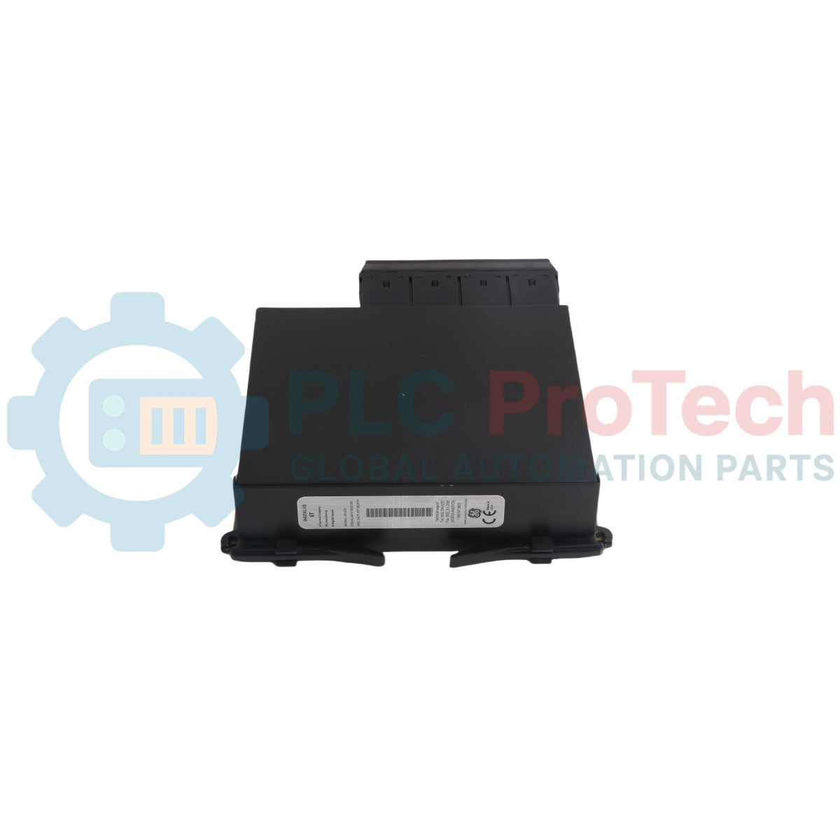
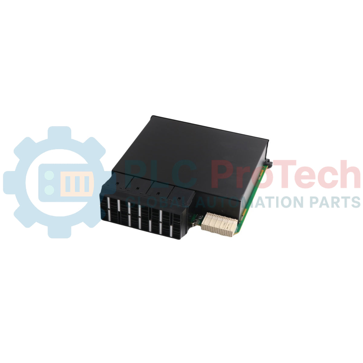
Le UR-6TH (UR6TH) fonctionne comme un module d’entrée/sortie numérique haute densité conçu pour la série de relais universels GE Vernova Multilin (UR). Ce bloc d’extension matériel s’intègre directement dans les châssis modulaires standard UR — tels que les relais de protection F60, L90, G60 et B30 — pour exécuter une logique d’interverrouillage rapide et une distribution télémétrique à travers les postes électriques et les systèmes énergétiques industriels lourds. Il comprend une combinaison embarquée de 8 entrées de contact et 4 sorties Form-A spécifiquement optimisée pour piloter des commandes de contrôle à haute vitesse.
Les sorties numériques Form-A fonctionnent sans surveillance interne des contacts, utilisant une conception mécanique avancée pour atteindre une durée de réponse inférieure à 4 ms. Ce profil de commutation ultra-rapide rend le matériel particulièrement adapté à une utilisation dans les circuits de déclenchement maître de disjoncteurs où l’interruption immédiate de l’arc et l’exécution de la séquence de protection sont obligatoires. Fonctionnant dans l’architecture native du micrologiciel du relais hôte, les chemins d’entrée et de sortie localisés sont gérés dynamiquement via des liaisons internes de backplane grâce au logiciel EnerVista UR Setup pour automatiser la cartographie des séquences et minimiser l’empreinte du câblage auxiliaire physique du panneau de contrôle.
Caractéristiques
Sorties Form-A à haute vitesse : Équipé de 4 contacts Form-A non surveillés offrant une vitesse de réponse ultra-rapide inférieure à 4 ms pour les applications de déclenchement direct du disjoncteur.
Acquisition dense de contacts : Dispose de 8 entrées de contacts indépendantes pour capturer les changements d’état discrets des équipements auxiliaires d’alimentation.
Intégration de la programmation FlexLogic : Cartographie complète des 8 entrées et 4 sorties dans l’éditeur FlexLogic interne pour une automatisation personnalisée, un déclenchement automatique en cas de surintensité et des schémas de blocage externes.
Réduction du câblage fixe : Réduit considérablement les infrastructures complexes de câblage secondaire dans les baies de panneaux de poste traditionnels grâce à une concentration locale numérique des points.
Compatibilité de tension flexible : Prend en charge les tensions de commande CC industrielles standard allant de 24 V CC à 250 V CC selon la configuration définitive du système.
Applications
Circuits de déclenchement direct (Trip) à haute vitesse pour disjoncteurs.
Réseaux d'interverrouillage et de signalisation automatisés pour équipements de sous-station.
Extensions de points d'entrée/sortie numériques pour les relais Multilin UR Series (F60, L90, G60, B30).
Systèmes de gestion d'énergie industrielle distribuée nécessitant une cartographie logique personnalisée.
24V DC à 250V DC (dépend du code de commande et de la configuration)
Outil de configuration
Logiciel de configuration EnerVista UR
Poids net
Environ 1,16 kg
Dimensions (H x L x P)
Environ 3,8 x 15,2 x 17,8 cm (H x L x P)
Directives d'installation
Vérification de la compatibilité matérielle
Lors du remplacement ou de la mise à niveau des cartes modulaires dans un système de relais actif, assurez-vous que les spécifications du nouveau module I/O correspondent parfaitement à la génération CPU et au type de châssis du relais hôte. Les cartes I/O Universal Relay varient considérablement dans la disposition des fonctionnalités, comme l'inclusion ou l'omission de la surveillance des contacts. Comparez toujours le code de commande alphanumérique complet imprimé sur la plaque signalétique principale du relais et vérifiez l'emplacement physique ciblé de la carte (généralement les emplacements G, H, M, N, P, U ou W) avant d'installer le matériel.
Isolation de l'alimentation avant installation
Déconnectez complètement l'alimentation auxiliaire principale AC/DC secondaire alimentant l'unité hôte du relais Universal.
Isolez ou verrouillez mécaniquement toutes les boucles externes de courant, de tension et de déclenchement de disjoncteur se terminant aux borniers externes de terrain afin d'éviter un déclenchement accidentel du disjoncteur de terrain pendant la procédure de remplacement.
Fixez solidement un bracelet antistatique (ESD) et connectez-le à une terre physique vérifiée pour protéger les microprocesseurs internes contre la dégradation due à l'électricité statique.
Extraction du module défectueux
Connectez un PC au relais et effectuez une sauvegarde complète des paramètres via le logiciel EnerVista UR, en enregistrant la configuration actuelle sous forme de fichier .urs.
Desserrez les fixations de la plaque frontale physique situées aux coins extérieurs supérieur et inférieur du cadre de l'emplacement I/O cible à l'aide d'un tournevis approprié.
Saisissez fermement les poignées d'extraction noires intégrées et tirez le module vers l'extérieur selon un chemin droit et uniforme pour désengager la carte de l'assemblage du bus arrière du backplane.
Insertion du nouveau module UR-6TH
Positionnez les bords latéraux verticaux de la nouvelle carte UR-6TH à l'intérieur des rails guides en plastique moulé de l'emplacement vide du châssis.
Faites glisser le module dans la cavité d'emplacement vide en douceur jusqu'à ce que la face avant extérieure soit affleurante avec les modules structurels adjacents.
Appliquez une pression horizontale ferme et centrée sur les bords de la face avant pour vous assurer que le connecteur arrière multipin s'insère complètement dans la prise du backplane.
Serrez les vis de retenue du panneau supérieur et inférieur pour assurer la stabilité mécanique et compléter la boucle de mise à la terre obligatoire du châssis.
Mise en service après installation
Réappliquez la distribution d'alimentation auxiliaire du système au module d'alimentation principal du châssis du relais.
Surveillez la routine d'auto-test automatisée via l'écran à cristaux liquides de la face avant ; confirmez qu'aucune alerte HARDWARE MISMATCH ni aucun drapeau de défaut critique de l'emplacement ne s'active.
Connectez-vous via la suite logicielle EnerVista, naviguez vers Statut -> Configuration matérielle, et vérifiez que le système énumère correctement le nouveau bloc matériel UR-6TH avant de restaurer l'opération en direct des boucles de déclenchement E/S externes.
FAQ
Quel type spécifique de contacts de commutation est fourni sur les canaux de sortie ?
Le module contient 4 sorties Form-A qui sont des contacts à un seul pôle et un seul contact normalement ouvert (SPST-NO). Ces sorties sont conçues sans composants internes de surveillance de courant ou de tension afin de maximiser la vitesse de commutation et de minimiser les délais de réponse sous 4 ms, ce qui les rend excellentes pour le routage brut de déclenchement de disjoncteur.
Ce module peut-il être positionné dans n'importe quel emplacement du châssis du relais universel ?
Non, ce module doit être positionné spécifiquement dans les emplacements standards désignés pour les E/S numériques. Ceux-ci correspondent aux emplacements G, H, M, N, P, U ou W dans l'architecture standard du châssis du relais universel, selon la manière dont votre code de configuration primaire spécifique est assigné.
Que se passe-t-il si la génération matérielle du module ne correspond pas au châssis du relais hôte ?
Si un conflit de génération matérielle survient entre la carte nouvellement insérée et le CPU hérité ou le firmware du backplane, la face avant du relais universel déclenchera un indicateur de défaut critique et affichera un état HARDWARE MISMATCH, bloquant l'exécution du logiciel opérationnel jusqu'à ce que les modules soient unifiés.
Livraison standard : 4 à 6 jours ouvrables via DHL, FedEx et UPS.
Expédition express : Expédition le jour même pour les commandes en stock passées avant 14h00 (GMT+8).
Couverture mondiale : Service dans plus de 150 pays, avec livraison rapide en Arabie Saoudite et aux Émirats Arabes Unis.
Retours et garantie
Garantie de 30 jours : Retours acceptés pour les produits en stock dans leur emballage d'origine scellé en usine.
Garantie de 12 mois : Chaque composant industriel est couvert par notre garantie technique professionnelle.
Les commandes sont traitées et livrées du lundi au vendredi (hors jours fériés).
Pour connaître l'éligibilité complète, les frais de restockage et les détails des retours internationaux, veuillez consulter notre site officiel
Politique de remboursement et de retour
.
Les données de maintenance relient les ordres de travail, les signaux des capteurs, l'historique des actifs, les coûts et les connaissances des techniciens. Bien utilisées, elles améliorent la...
Cet article explique comment les actionneurs électriques intégrés, tels que la série e-Actuator de SMC, transforment le contrôle de mouvement industriel en remplaçant les systèmes pneumatiques et...
Cet article explique comment les systèmes PLC réalisent les opérations mathématiques de base telles que l'addition, la soustraction, la multiplication, la division, le modulo et l'exponentiation dans...
L'article explique plusieurs fonctions avancées de logique booléenne utilisées en programmation d'automates programmables industriels (API) au-delà des opérations de base ET, OU et NON. Il couvre...
La logique booléenne est la base de tout programme PLC. Des commandes machines simples aux systèmes d'automatisation industrielle complexes, les portes logiques déterminent comment les contrôleurs...
Les pare-feux industriels jouent un rôle crucial dans la cybersécurité OT, protégeant les réseaux PLC, DCS et SCADA grâce à la segmentation, au contrôle des entrées/sorties et à l’intégration IDS/IPS...
Choisir une sélection entraîne un rafraîchissement complet de la page.