Description
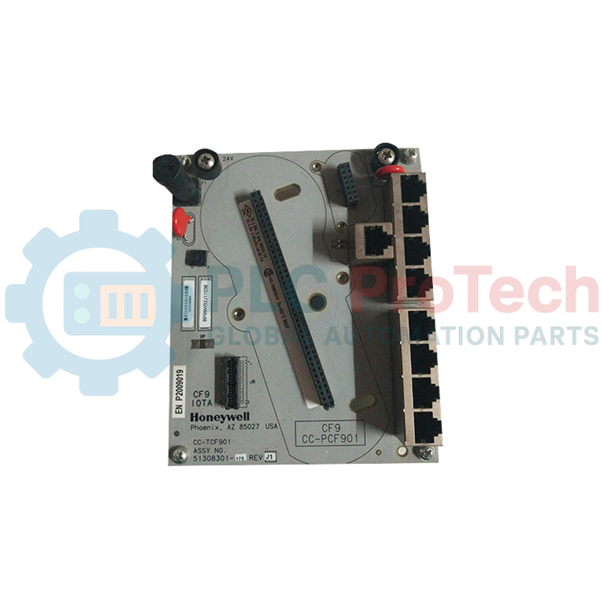
Designed to facilitate secure physical termination and robust fault-tolerant routing within Experion C300 control networks, the Honeywell CC-TCF901 serves as a high-integrity 9-port Control Firewall Input Output Termination Assembly (IOTA). This unit provides the foundational backplane interface for the active CC-PCF901 Control Firewall module, segregating in-cabinet traffic from the wider supervisory control network. By integrating dedicated physical terminal connections for Fault Tolerant Ethernet (FTE), this assembly protects local controller communication loops against broadcast storms and unauthorized network access. The hardware architecture features built-in 24 VDC power distribution routing to supply connected modules directly through the backplane connections, eliminating the need for redundant external terminal blocks inside the cabinet.
Features
- Provides eight dedicated, high-speed RJ-45 connection points for routing FTE cabling from in-cabinet controllers and Series C Fieldbus Interface Modules (FIMs).
- Features a designated 9th port serving as a secure uplink path to the FTE supervisory and control network layers.
- Built-in power routing pathways distribute continuous 24 VDC to the active control firewall module.
- Compatible with optional plug-in media converter modules, allowing integration of single-mode (Ca-FSMx01) and multi-mode (Ca-FMMx01) fiber-optic runs.
- Robust mechanical footprint designed for direct mounting on standard Honeywell Series C channel assemblies or DIN-rail environments.
Applications
- Honeywell Experion PKS C300 Controller Cabinet Integration
- Series C Fieldbus Interface Module (FIM) Network Segregation
- Critical Ethernet Network Path Redundancy & Segment Isolation
- In-Cabinet Control Node Fireproofing and Noise Shielding
Technical Specifications
| Specification Parameter |
Value / Detail |
| Manufacturer |
Honeywell |
| Model / Part Number |
CC-TCF901 |
| Product Series |
Experion Series C |
| Module Type |
9-Port Control Firewall IOTA (Input Output Termination Assembly) |
| RJ-45 Ethernet Ports |
9 Ports Total (8 Controller/FIM FTE Ports, 1 Uplink FTE Port) |
| Nominal Operating Voltage |
24 VDC |
| Maximum Current Supply Rating |
0.30 A (300 mA) @ 24 VDC |
| Supported Fiber Modules |
Ca-FSMx01 (Single Mode), Ca-FMMx01 (Multi-Mode) |
| Compatible Firewall Module |
CC-PCF901 Control Firewall Module |
| Operating Temperature Range |
0 to 60 degC |
| Country of Origin |
United States |
| Shipping Weight (Calculated) |
2.0 kg |
| Package Dimensions (Calculated) |
16.5 cm x 14.5 cm x 10.0 cm |
Connections and Interfaces
| Connector / Terminal |
Functional Circuit Assignment |
| Ports 1 through 8 (RJ-45) |
Downstream nodes (C300 Controllers and Fieldbus Interface Modules) |
| Port 9 (RJ-45) |
Dedicated FTE Uplink to supervisory plant LAN / network switch |
| 24V DC Terminals |
Primary & Redundant internal power rail input to drive the firewall active card |
| Chassis Ground |
Low-impedance grounding connection to main cabinet copper ground busbar |
Empirical Engineering Insights
Alternative Models & Compatibility
The CC-TCF901 is mechanically key-coded to only accept the CC-PCF901 active control firewall module. Always verify that your active module firmware (experion system release) matches the specific hardware revisions of the baseplate to prevent initialization failures during hot-replacement operations. Do not attempt to mount standard non-firewall Honeywell Series C I/O modules on this assembly, as internal keying pins prevent incorrect mating.
Application Pitfalls & Engineering Notes
To maintain full Fault Tolerant Ethernet (FTE) functionality, verify that the yellow and green STP/UTP cables are connected to the designated redundant paths. Standardizing connection patterns (e.g., using Ports 1-4 for Yellow segment and Ports 5-8 for Green segment) simplifies cabinet topology audits. Keep cabling neat and avoid physical proximity to high-current AC motor starter lines, which can induce noise on unshielded RJ-45 jumpers.
Commissioning & Wiring Tips
When connecting fiber media converter modules to the CC-TCF901, always ensure clean optical fiber connections. Dust contamination is the leading cause of packet drop errors on the supervisory uplink (Port 9). Use a fiber cleaning kit to wipe optical faces prior to inserting into the Ca-FSMx01 or Ca-FMMx01 receiver slots.
Installation Guidelines
CRITICAL SAFETY WARNING
Isolate and completely de-energize all primary and redundant 24 VDC power sources supplying the cabinet backplane before attempting installation, removal, or terminal routing changes of the CC-TCF901 base IOTA. Failure to isolate power can result in transient arcs, potentially causing system lockups on adjacent C300 controllers or damaging sensitive active communication modules.
1
Mount the CC-TCF901 IOTA carrier securely onto the cabinet mounting channel or DIN rail. Ensure proper grounding through the carrier surface to the cabinet backplate.
2
Verify grounding continuity. Connect a heavy-gauge copper grounding wire from the designated ground stud on the IOTA to the common enclosure ground busbar.
3
Terminate the primary and auxiliary 24 VDC power supply lines directly to the power inputs on the carrier plate, maintaining strict polarity.
4
Plug standard RJ-45 Ethernet cables from the in-cabinet C300 controllers or FIM units into Ports 1 through 8. Connect the supervisory FTE uplink cable to Port 9.
5
Carefully align and mate the active CC-PCF901 Control Firewall module with the multi-pin connector on this CC-TCF901 base, then tighten mounting fasteners securely.