Description
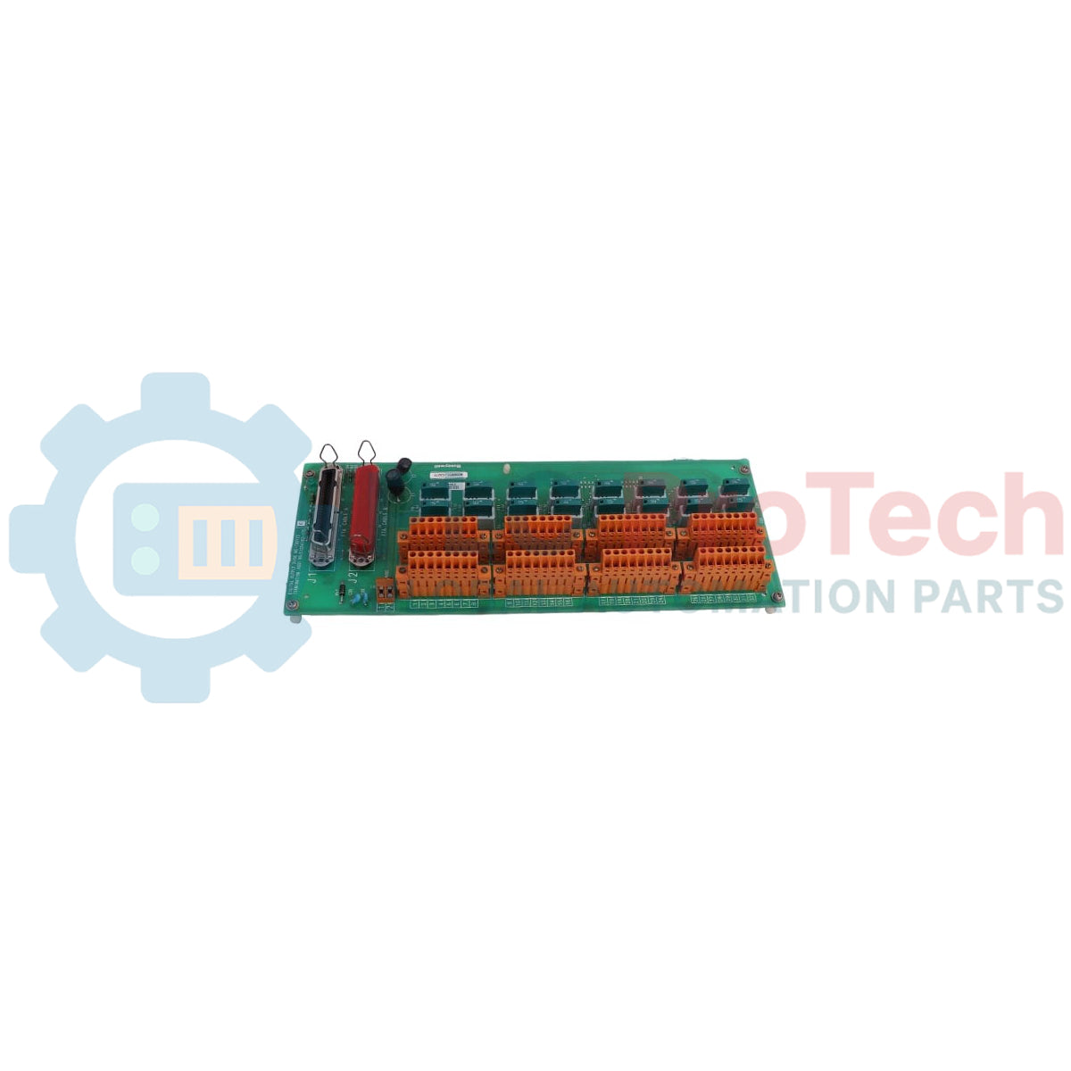
Providing secure interface routing for safety-critical control systems, the Honeywell FS-TSRO-0824 serves as an 8-channel digital output field termination assembly (FTA) designed for high-integrity safety environments. This module acts as the physical interface between the Safety Manager/FSC control processor and the field-side actuators, solenoids, or indicators. Featuring 8 isolated relay channels with individual fuse protection, it guarantees reliable safety loop execution up to AK1-6 safety classes. The hardware is built to isolate high field-side switching voltages from sensitive system logic, preventing faults from propagating back into the controller backplane.
Features
-
8 Isolated Relay Output Channels: Provides complete physical and electrical isolation between control logic and field-side circuits.
-
High Switching Capacity: Capable of handling up to 250 Vac/Vdc for versatile application across AC and DC control loops.
-
Overcurrent Protection: Features individual 5 A fusing per channel to protect field wiring and relay contacts from short-circuits.
-
Broad System Compatibility: Fully compatible with Honeywell Safety Manager and legacy FSC safety systems.
-
Industrial Durability: Robust DIN-rail mountable carrier panel engineered to withstand harsh marshalling cabinet conditions.
Applications
- Emergency Shutdown (ESD) systems in petrochemical and refining facilities.
- Critical Burner Management Systems (BMS) requiring discrete safety outputs.
- Fire and Gas (F&G) loop alarm and beacon execution.
- High-Integrity Pressure Protection Systems (HIPPS) interlocks.
Technical Specifications
| Parameter |
Specification Value |
| Manufacturer |
Honeywell |
| Model Number |
FS-TSRO-0824 |
| Module Type |
Digital Output Field Termination Assembly (FTA) |
| Safety Class Certification |
AK1 through AK1-6 |
| Number of Output Channels |
8 |
| Nominal Input Voltage |
24 Vdc |
| Maximum Input Voltage |
36 Vdc |
| Relay Pick-up Voltage |
19.2 Vdc |
| Typical Input Current |
40 mA at 24 Vdc |
| Maximum Output Current |
5 A per channel (fused) |
| Minimum Output Current |
1 mA at 5 V |
| Maximum Output Voltage |
250 Vac / 250 Vdc |
| Maximum Switched Load |
1250 VA (AC) / 150 W (DC) |
| Physical Dimensions (L x W x H) |
300 mm x 70 mm x 60 mm |
| Shipping Weight |
2.0 kg |
Empirical Engineering Insights
Alternative Models & Compatibility
The FS-TSRO-0824 operates natively within the Safety Manager and FSC control system lines. While standard 24 Vdc outputs map directly, check system controller firmware revisions to verify that all integrated diagnostics support the loop architecture. This FTA serves as an operational replacement for legacy, non-fused field termination systems to improve field-side circuit protection.
Application Pitfalls & Engineering Notes
When switching highly inductive field loads (such as solenoid valves or large contactor coils), inductive kickback can cause arc damage across the internal relay contact points. To preserve the service life of the contacts and maintain safety-loop availability, external RC snubber networks (for AC loops) or free-wheeling diodes (for DC loops) must be installed directly across the load. Do not exceed the collective current dissipation limits of the marshalling cabinet when operating all 8 channels continuously at maximum load.
Commissioning & Wiring Tips
Verify the rating of installed fuses prior to loop energization. Standard commissioning diagnostics should include a wire-insulation and loop-resistance check from the terminal block to the field element to verify that no dead-shorts exist, which would immediately blow the onboard 5 A protection fuses.
Installation Guidelines
CRITICAL WARNING: Isolate and lock out all control and field-side power sources prior to accessing terminal blocks, system cables, or onboard fuses. Failure to de-energize circuits may result in severe shock hazard, accidental activation of safety-critical elements, or equipment damage.
1
Mount the FTA assembly securely onto standard DIN-rail or dedicated column support plates inside the marshalling enclosure.
2
Connect the multi-pin system interface cable from the Safety Manager digital output module to the FTA card socket, ensuring positive lock mechanics are engaged.
3
Terminate field wiring onto the screw terminal blocks. Maintain clean separation between low-voltage safety logic and high-voltage field wiring runs.
4
Install the 5 A channel fuses, verify loop configuration, and apply primary control power followed by field loop supply.