Présentation du produit
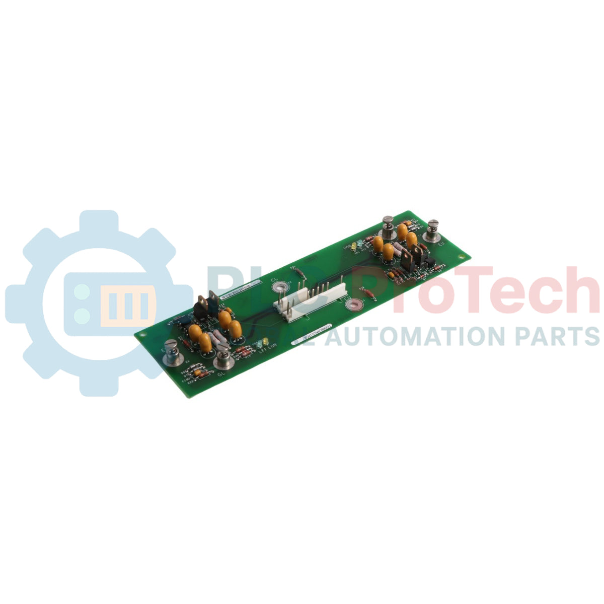
Le IS200DAMCG1ACB sert de circuit amplificateur de commande de grille et de carte d’interface clé dans le système de contrôle GE Mark VI Speedtronic. Conçu spécifiquement pour les applications de conversion de puissance élevée, ce circuit agit comme le lien de commande critique entre la logique de contrôle et les transistors bipolaires à grille isolée intégrés (IGBT). Le IS200DAMCG1ACB capte les signaux logiques de faible niveau et les amplifie en signaux de commande de grille robustes capables de commuter de grands modules de puissance à haute fréquence. En intégrant à la fois l’amplification et la surveillance du retour, cette carte assure la synchronisation précise requise pour les entraînements moteurs lourds et les systèmes d’excitation de turbines, protégeant la chaîne de puissance contre l’instabilité électrique.
Avantages techniques principaux
Contrôle précis de la commutation des IGBT
La carte intègre un circuit pilote spécialisé qui optimise les caractéristiques de mise en marche et d’arrêt des modules IGBT. En contrôlant précisément le courant de grille, le IS200DAMCG1ACB minimise les pertes de commutation et réduit les interférences électromagnétiques (EMI), prolongeant directement la durée de vie opérationnelle des semi-conducteurs de puissance principaux.
Protection intégrée contre les défauts
La logique matérielle avancée du IS200DAMCG1ACB surveille les événements de désaturation et les conditions de surintensité. En cas de détection d’un défaut au niveau de l’IGBT, la carte initie une « extinction douce » localisée pour éviter une défaillance thermique catastrophique, communiquant l’état du défaut au rack de contrôle Mark VI via l’interface à haute vitesse.
Isolation robuste des signaux
Pour protéger les processeurs de contrôle sensibles contre l’étage de puissance haute tension, la carte utilise des optocoupleurs haute performance ou des isolateurs magnétiques. Cette séparation galvanique garantit que les transitoires sur le bus de puissance ne migrent pas dans le réseau de contrôle, maintenant la disponibilité du système même lors de perturbations du réseau.
Spécifications techniques
| Paramètre |
Spécification |
| Plateforme du système de contrôle |
GE Mark VI Speedtronic |
| Fonction de la carte |
Amplificateur de commande de grille & interface de retour |
| Compatibilité IGBT |
Modules IGBT haute puissance standard |
| Indice d’isolation |
Jusqu’à 2500 V RMS |
| Tension logique d’entrée |
5 V DC / 24 V DC (selon interface) |
| Fréquence de fonctionnement |
Optimisée pour commutation PWM jusqu’à 20 kHz |
| Exigences de refroidissement |
Convection ou air forcé (selon application) |
| Conformité |
Normes UL, CE et IEEE en électronique de puissance |
Guide d’installation et de maintenance
Manipulation et protection ESD
Le IS200DAMCG1ACB contient des composants MOS à grille très sensibles. Utilisez toujours un bracelet antistatique relié à la terre et des tapis conducteurs lors de l’installation. Évitez de toucher les connecteurs dorés en bordure ou les résistances de grille montées en surface pour prévenir tout dommage latent dû aux décharges électrostatiques.
Séquencement des connexions
Lors de l’intégration de la carte avec le module IGBT, assurez-vous que les paires torsadées gate-émetteur soient aussi courtes que possible afin de minimiser l’inductance parasite. Vérifiez que l’interface à fibre optique ou câble ruban vers le rack de contrôle est bien connectée avant d’appliquer la tension haute tension du bus DC.
Interprétation des LED de diagnostic
Surveillez les LED de statut embarquées lors de l’auto-test au démarrage (POST). Une lumière verte fixe indique généralement que les alimentations internes (VCC/VEE) sont dans la tolérance, tandis qu’une LED rouge ou ambre clignotante signale un défaut de grille ou un signal de retour hors plage provenant du pont de puissance.
Avantages d’ingénierie
Le IS200DAMCG1ACB est conçu pour les environnements industriels lourds, notamment les centrales à turbines à gaz et les grandes installations de fabrication. Sa conception multi-couches intègre des plans de masse dédiés pour supprimer le bruit, garantissant une performance stable à proximité des barres omnibus à fort courant. En tant que composant natif Mark VI, il offre une intégration transparente avec le logiciel ToolboxST de GE, permettant une surveillance en temps réel de la santé de la commande de grille et une simplification du dépannage à distance.
FAQ techniques
Q1 : Le IS200DAMCG1ACB peut-il remplacer les anciennes versions DAMC ?
R1 : Oui, le suffixe « G1ACB » indique un niveau de révision spécifique qui inclut généralement des améliorations matérielles par rapport aux versions antérieures. Il est rétrocompatible avec la plupart des applications de commande de grille Mark VI, à condition que le firmware du système prenne en charge l’ID de révision.
Q2 : Qu’est-ce qui cause un « défaut de désaturation » sur cette carte ?
R2 : Un défaut de désaturation se produit si l’IGBT ne peut pas s’enclencher complètement ou si une condition de surintensité le force hors de sa région de saturation. La carte détecte la montée de la tension Vce résultante et inhibe immédiatement la commande de grille pour éviter l’explosion de l’IGBT.
Q3 : Cette carte nécessite-t-elle une alimentation externe ?
R3 : La carte puise généralement l’alimentation logique depuis le backplane Mark VI ou un bus de distribution 24 V DC dédié. Cependant, l’énergie de commande de grille haute tension est gérée en interne via des convertisseurs DC-DC embarqués pour maintenir l’isolation.
Q4 : Comment vérifier les résistances de grille lors de la maintenance régulière ?
R4 : Lors des arrêts programmés, utilisez un multimètre de précision pour vérifier que les résistances de grille correspondent aux valeurs spécifiées dans le schéma de votre système. Des résistances décolorées ou carbonisées indiquent une chaleur excessive due à la commutation et la carte doit être remplacée de manière proactive.