Présentation du produit
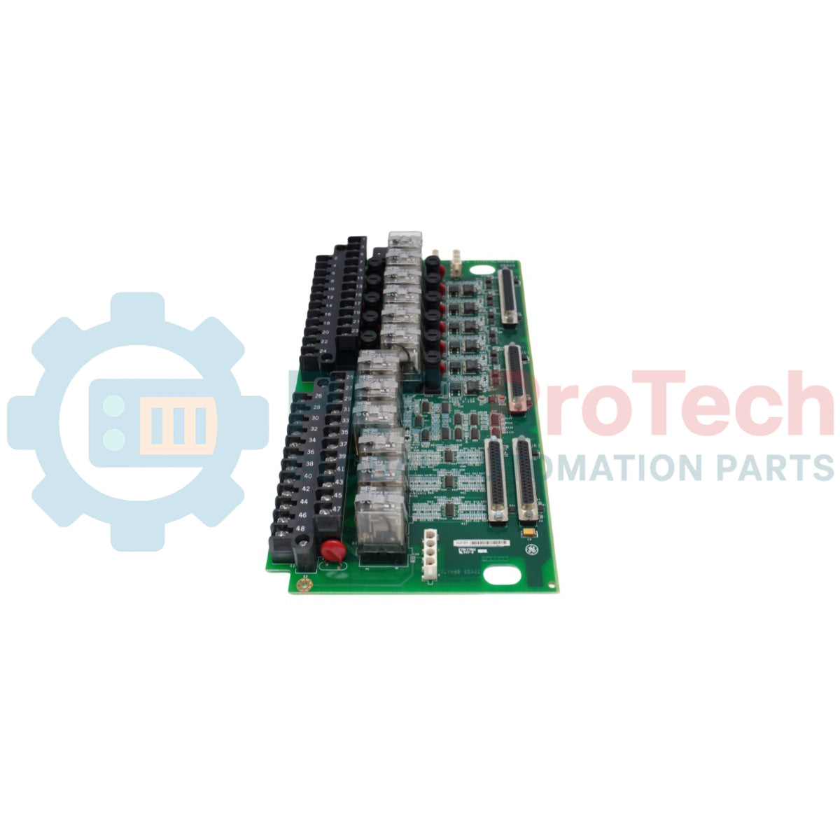
Le IS200TRLYH1B sert de carte de sortie relais à haute densité (TRLY) dans le système de contrôle GE Mark VI Speedtronic. Cette carte fournit l'interface essentielle pour les fonctions de contrôle auxiliaires nécessitant des sorties à contact sec pour piloter des équipements externes. Contrairement à la carte TREG axée sur les urgences, le IS200TRLYH1B gère la logique à usage général, comme le démarrage des pompes moteur, l’activation des ventilateurs d’enceinte et la signalisation aux systèmes DCS distants. Il prend en charge les configurations Simplex et Triple Modular Redundant (TMR), recevant les signaux de commande des processeurs E/S et les convertissant en états physiques robustes de commutation. Avec ses blocs de bornes intégrés et ses connecteurs à ruban standardisés, la carte TRLY simplifie le câblage des armoires tout en maintenant la haute isolation électrique nécessaire à la fiabilité des centrales électriques.
Avantages techniques principaux
Contrôle auxiliaire à haute densité
Le IS200TRLYH1B regroupe de 12 à 24 canaux relais indépendants (selon la configuration) sur un seul circuit imprimé. Cette disposition à haute densité réduit l’encombrement dans l’armoire de contrôle, permettant de gérer des séquences d’automatisation complexes — telles que la gestion du système d’huile de lubrification ou la séquence d’eau de refroidissement — à partir d’un nœud matériel centralisé.
Architecture de vote TMR flexible
Lorsqu’il est utilisé dans un système TMR, la carte accepte les entrées de contrôle des cœurs <R>, <S> et <T>. Le matériel exécute un processus de vote 2-sur-3 pour chaque sortie, garantissant qu’une défaillance d’un seul câble de contrôle ou processeur ne provoque pas un changement d’état non désiré de l’équipement auxiliaire.
Surveillance diagnostique embarquée
La carte TRLY fournit un « retour de contact » en temps réel au système Mark VI. Elle surveille la continuité des bobines de relais et l’état des contacts de sortie. Si un relais ne bascule pas après une commande, la carte génère immédiatement une alarme « Incohérence logique », permettant aux opérateurs d’identifier le canal défectueux sans avoir à tracer manuellement le circuit.
Spécifications techniques
| Paramètre |
Spécification |
| Plateforme de contrôle |
Mark VI Speedtronic |
| Fonction de la carte |
Sortie relais auxiliaire (TRLY) |
| Type de relais |
Relais électromécaniques scellés |
| Configuration des contacts |
Forme-C (SPDT) ou Forme-A (SPST) |
| Capacité maximale des contacts |
125V DC @ 2A / 250V AC @ 5A |
| Temps de réponse |
< 10ms (typique) |
| Force d’isolation |
1,5 kV entre bobine et contacts |
| Niveau de révision |
H1B (révision fiabilité améliorée) |
Guide d’installation et de maintenance
Câblage des blocs de bornes et manchons
Le IS200TRLYH1B dispose de deux rangées de bornes à vis robustes. Utilisez un fil de 1,5 mm² (16 AWG) pour les circuits de commande et appliquez toujours des manchons isolés pour éviter les courts-circuits dus aux « cheveux errants ». Serrez toutes les bornes à 0,56 Nm (5 in-lb). Veillez à ce que les câblages AC et DC soient acheminés dans des goulottes séparées pour minimiser les couplages inductifs parasites.
Protection par fusibles et remplacement
La plupart des variantes TRLY incluent des fusibles individuels ou des limiteurs sans fusible pour les canaux de sortie. Si un relais spécifique ne commande pas l’équipement de terrain, vérifiez la continuité du fusible associé. Remplacez toujours les fusibles par ceux spécifiés par GE avec l’ampérage exact afin d’éviter d’endommager les pistes internes en cuivre de la carte lors d’un court-circuit sur le terrain.
Acheminement des câbles à ruban
Connectez la carte TRLY aux cartes processeurs VCMI ou VRTD à l’aide des câbles à ruban 50 broches. Assurez-vous que les câbles sont éloignés des barres omnibus AC à fort courant. Utilisez les languettes de verrouillage intégrées sur les connecteurs de la carte pour empêcher que les câbles ne se desserrent avec les vibrations, cause fréquente d’alarmes intermittentes « Échec de communication E/S ».
Avantages d’ingénierie
Le IS200TRLYH1B est conçu pour résister aux conditions thermiques et électriques sévères d’une enceinte de turbine. La révision H1B utilise des contacts de relais plaqués or pour prévenir l’oxydation dans les applications à faible signal (contact sec), garantissant une fiabilité de commutation à long terme. Étant un composant natif Mark VI, il s’intègre parfaitement au logiciel de configuration ToolboxST, permettant l’assignation logique par glisser-déposer et les tests forcés en temps réel pour la mise en service et le dépannage.
FAQ techniques
Q1 : Le IS200TRLYH1B peut-il être utilisé pour les fonctions d’arrêt d’urgence (E-Stop) ?
A1 : Bien que la carte TRLY soit très fiable, elle est destinée au contrôle auxiliaire. Les fonctions critiques de déclenchement d’urgence doivent être acheminées via la carte TREG, qui dispose du vote matériel spécialisé 2-sur-3 requis pour les chaînes de sécurité turbine.
Q2 : Quel est l’avantage de la révision H1B par rapport aux versions antérieures ?
A2 : La révision H1B inclut généralement une meilleure résistance aux vibrations des relais et une disposition optimisée du circuit imprimé pour une meilleure dissipation thermique. C’est un remplacement direct « forme-ajustement-fonction » des anciennes cartes TRLY, mais avec un MTBF supérieur en environnements à forte vibration.
Q3 : Comment tester un canal relais spécifique sans faire tourner la turbine ?
A3 : Avec la station de maintenance Mark VI, vous pouvez « forcer » le bit de sortie numérique associé au relais. Observez la LED embarquée (si disponible) et utilisez un multimètre pour vérifier la continuité aux points de terminaison. Assurez-vous que tous les interverrouillages terrain sont levés avant de forcer les sorties.
Q4 : Cette carte supporte-t-elle simultanément des charges 110V AC et 125V DC ?
A4 : Oui, à condition que les charges soient connectées à des canaux relais différents. Chaque relais est galvanquement isolé des autres, ce qui permet de mélanger les tensions AC et DC sur la même carte, tout en maintenant une séparation adéquate dans les goulottes de câblage externes pour la sécurité.