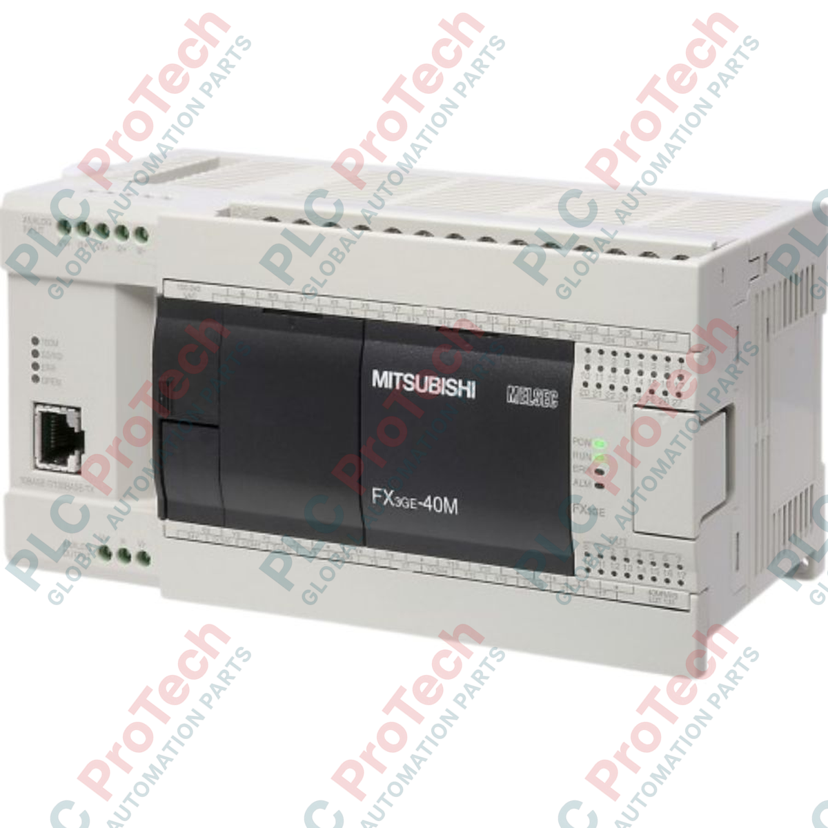
Description
Managing complex industrial tasks with localized automation is streamlined using the Mitsubishi Electric FX3GE-40MT/ES programmable logic controller. This compact, all-in-one base unit integrates high-performance microprocessing with built-in digital inputs, transistor outputs, analog processing, and dual communication interfaces. Engineered as an extension of the reliable MELSEC FX3G architecture, this controller features embedded Ethernet and USB ports, eliminating the need for external expansion cards in space-constrained control panels.
Features
-
High-Speed Processing: Incorporates dual-layer architecture supporting standard program capacity up to 32,000 steps.
-
Built-In Ethernet: Standard RJ45 port supporting 10BASE-T/100BASE-TX for seamless SCADA, HMI, and network integration.
-
Integrated Analog I/O: Factory-configured with 2 channels of analog input and 1 channel of analog output.
-
Positioning Capabilities: High-speed counter inputs up to 60 kHz and positioning pulse outputs up to 100 kHz.
-
Flexible Expansion: Scalable layout utilizing FX3 series expansion boards and special function blocks.
Applications
- Packaging and automated sealing systems.
- Local water treatment plants and pumping stations.
- Conveyor networks and automated materials handling.
- HVAC monitoring and remote telemetry systems.
Technical Specifications
| Parameter |
Specification |
| Manufacturer |
Mitsubishi Electric |
| Model / Article Number |
FX3GE-40MT/ES |
| Series |
MELSEC FX3GE |
| Rated Power Supply |
100 to 240 V AC (+10% / -15%), 50/60 Hz |
| Total Integrated I/O Points |
40 points |
| Digital Inputs |
24 Inputs (24V DC, Sink/Source selected by terminal) |
| Digital Outputs |
16 Outputs (Transistor, Sink) |
| Integrated Analog Inputs |
2 Channels (0-10V DC / 4-20mA) |
| Integrated Analog Outputs |
1 Channel (0-10V DC / 4-20mA) |
| Communication Ports |
Ethernet (RJ45), USB (Mini-B), RS-422 |
| Memory Capacity |
32,000 steps internal EEPROM program memory |
| Operating Temperature Range |
0 to 55 degC (32 to 131 Fahrenheit) |
| Net Weight |
0.8 kg |
| Dimensions (W x H x D) |
175 mm x 90 mm x 86 mm |
Connections and Interfaces
| Terminal Label |
Function / Assignment |
| L / N |
100-240 V AC Main Power Supply input |
| 24V / 0V |
Auxiliary 24V DC sensor power output supply |
| S/S |
Sink/Source selector terminal for digital inputs |
| X000 - X027 |
24V DC Digital Inputs (high-speed counters on first channels) |
| Y000 - Y017 |
Transistor Sink Outputs (pulse output functionality on Y000-Y002) |
| V1+, I1+, VI1-, V2+, I2+, VI2- |
Analog Inputs (Channel 1 and Channel 2 voltage/current terminals) |
| V3+, I3+, VI3- |
Analog Output (Channel 3 voltage/current terminals) |
Empirical Engineering Insights
Alternative Models & Compatibility
The FX3GE-40MT/ES offers a direct physical upgrade path for older FX1N-40MT-D and standard FX3G-40MT/ES micro-controllers. Existing FX3G ladder code is fully backward compatible. However, to access the built-in Ethernet parameters and configure analog channels directly without from/to instructions, software development must be completed in GX Works2 (version 1.98 or later).
Application Pitfalls & Engineering Notes
This controller features standard Transistor Sink outputs (indicated by the MT suffix). Connecting field loads wired as sink logic to an improper polarity source will destroy the internal optocouplers. Ensure that external auxiliary power supplies are properly bonded. Thermal dissipation issues can manifest inside sealed control cabinets if the unit is installed horizontally; strictly adhere to vertical wall-mount layouts allowing a minimum clearance of 50mm above and below the chassis for natural convection airflow.
Commissioning & Wiring Tips
To prevent electrical noise interference on the integrated analog channels, always separate the 0-10V / 4-20mA routing from high-current AC power cables. Run shielded twisted-pair (STP) wiring for analog loops and terminate the shield ground strictly at the PLC end to block localized ground loop currents from destabilizing sensor values.
Installation Guidelines
CRITICAL WARNING:
Isolate all main power sources prior to conducting installation, mounting, or termination work. Failure to de-energize external circuits can cause severe electrical shock, hardware failure, or unexpected movement of connected actuators.
1
Mount the controller onto a standard 35mm DIN rail or secure it to a flat backplate using integrated M4 mounting screw points.
2
Connect the main 100-240 V AC supply source to the terminal block, ensuring correct protective grounding (PE) alignment.
3
Wire input lines with the selected active polarity (Sink or Source orientation configured through the S/S terminal).
4
Connect program transmission via Ethernet or USB, launch GX Works2, and run diagnostic procedures to verify hardware registers.