Description
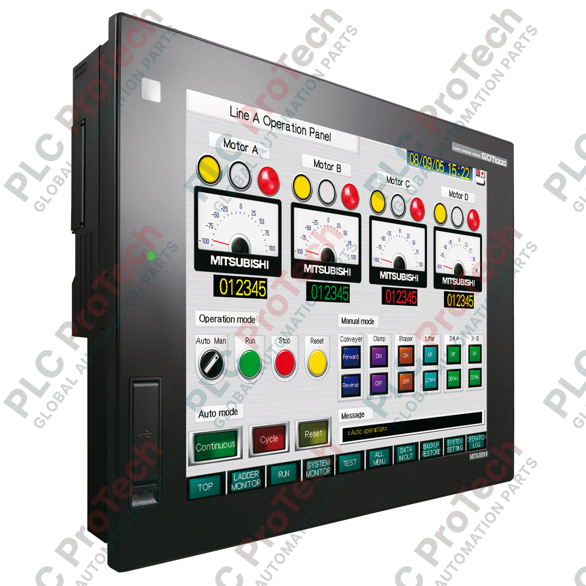
Tasked with local machine visualization and real-time operator interface control, the Mitsubishi Electric GT1155-QTBD serves as a high-resolution, hardware-integrated human-machine interface designed for industrial control cabinets. This GOT1000 Series unit provides operators with crisp 256-color visual telemetry and multi-touch response capabilities across a 5.7-inch active matrix screen, minimizing manual console overhead. Built with a robust physical chassis, it houses an internal 3 MB flash memory to store native OS programs and project graphics, alongside a dedicated battery-backed SRAM storage bank for non-volatile alarm tracking and parameter recipes. Highly optimized for integration with MELSEC controllers and external automation networks, this unit operates efficiently under harsh factory floor environments, offering exceptional resistance against mechanical vibration and high ambient operating temperatures.
Key Features
-
High-Resolution Display: 5.7-inch TFT color liquid crystal display featuring 320 x 240 pixel resolution and 256-color rendering for high visual clarity.
-
Industrial-Grade Touch Grid: Matrix-resistive interface with 300 active touch points, allowing a maximum of 2 simultaneous contacts.
-
Dual-Storage Architecture: Built-in 3 MB Flash memory for primary system configurations alongside a 512 KB battery-backed SRAM.
-
Flexible Mounting Orientations: Certified for vertical and horizontal installations with calibrated thermal performance configurations.
-
Rugged Electrical Design: Classified under Overvoltage Category II and Pollution Degree 2, matching industrial standard panel ratings.
Heavy Industrial Applications
-
Automotive Assembly Terminals: Localized process tracking and robotic cell diagnostics on production floors.
-
Packaging and Sorting Systems: High-speed material handling control, recipe adjustment, and status monitoring.
-
Water Treatment Control Cabinets: Outdoor-protected field panels managing pumping telemetry and valve sequences.
-
Localized Machine Tooling: OEM machine visualization requiring localized system interaction and safety alarms.
Technical Specifications
| Manufacturer |
Mitsubishi Electric |
| Model / Reference |
GT1155-QTBD |
| Display Technology |
TFT Color Liquid Crystal |
| Diagonal Screen Size |
5.7 Inches (115 mm x 86 mm active display area) |
| Native Resolution |
320 x 240 Dots |
| Supported Colors |
256 Colors |
| LCD Intensity |
400 cd/m2 (Adjustable over 8 software levels) |
| Backlight Lifespan |
Approx. 50,000 Hours (at ambient temperature of 25 degC) |
| Touch Key Configuration |
300 matrix keys per screen (15 lines x 20 columns) |
| Project Flash Memory (C Drive) |
3 Megabytes (100,000 write cycles maximum) |
| Internal SRAM (D Drive) |
512 Kilobytes (Battery-backed) |
| Data Retention Battery |
GT11-50BAT Lithium Battery (approx. 5-year lifespan) |
| Operating Temperature (Display) |
0 to 50 degC |
| Operating Temp (Chassis) |
0 to 55 degC (Horizontal mount); 0 to 50 degC (Vertical mount) |
| Ambient Humidity Limit |
10% to 90% RH, non-condensing |
| Vibration/Shock Resistance |
Compliant with JIS B3502 and IEC 61131-2 standards |
| Device Protection Class |
Overvoltage Category II, Pollution Degree 2 |
| Grounding Requirements |
Class D grounding (100 Ohms or less) |
| Net Weight |
0.7 Kilograms (Excluding mounting fixtures) |
| Shipping Weight (Calculated) |
8.0 Kilograms |
Empirical Engineering Insights
Alternative Models & Compatibility
This touch screen belongs to the GOT1000 legacy tier. When replacing legacy GOT900 units with this model, engineers must use GT Designer3 software to convert the older graphic assets and map corresponding communication parameters. Ensure you confirm the system memory footprint before flashing converted software files, as the C-drive storage is capped at 3 MB.
Application Pitfalls & Engineering Notes
Operating performance is directly linked to mounting orientation. Mounting the touch screen vertically reduces the maximum safe operational temperature range of the chassis housing by 5 degC (down to 50 degC). If installed within enclosed, non-ventilated control panels alongside high-dissipation components such as variable frequency drives or large power supplies, cooling fans should be incorporated to prevent rapid thermal aging of the LCD panel.
Commissioning & Wiring Tips
Avoid running communication cables parallel to high-voltage power lines to prevent Electromagnetic Interference (EMI) issues. Always implement dedicated Class D grounding with a loop resistance of 100 Ohms or less. When a separate earth connection cannot be established, bridge the grounding tab directly to the metal backplane of your control cabinet, ensuring all paint and oxidation layers are cleared from the contact point.
Installation Guidelines
CRITICAL SAFETY WARNING
Isolate and de-energize all power distribution blocks leading to the control panel before initiating unit installation. Failure to bleed residual capacitive charges or working on live lines can cause immediate terminal damage, control bus failure, or personnel injury.
1
Cut a clean opening in the control panel door matching the precise dimensional layout specifications of the housing bezel.
2
Apply the waterproof packing seal around the bezel groove to maintain IP protection ratings before inserting the device into the cutout.
3
Insert and finger-tighten the mounting brackets on the rear tracks, then torque them systematically to prevent distortion of the touch glass.
4
Connect the dedicated ground terminal block to the Class D ground path before connecting auxiliary power and communication buses.