Description
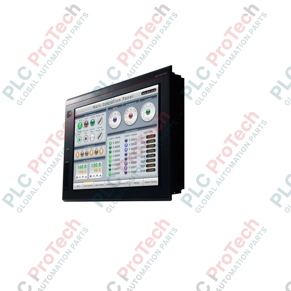
Facilitating high-resolution operational control and monitoring in distributed automation systems, the Mitsubishi Electric GT2510-WXTBD serves as a robust widescreen operator interface within the GOT2000 GT25 Series. This 10.1-inch WXGA HMI features a high-density 1280 x 800 TFT color display capable of rendering complex graphical diagnostics, detailed trends, and plant schematics with exceptional clarity. Operating on a 24V DC power supply, the unit integrates seamlessly into industrial control panels, providing advanced data processing, multi-channel communication, and secure user access. Equipped with built-in Ethernet, Serial, and USB interfaces, it functions as a centralized data hub that bridges field-level PLCs, variable speed drives, and higher-level SCADA networks.
Features
-
High-Resolution WXGA Display: 10.1-inch wide TFT color screen with a resolution of 1280 x 800 dots, delivering sharp text and realistic graphical objects.
-
Analog Resistive Touch Panel: High-durability single-touch resistive film allows reliable operation even when operators are wearing heavy industrial gloves.
-
Robust Interface Selection: Built-in support for Ethernet (100Base-TX/10Base-T), RS-232, RS-422/485, USB Host (Type A), USB Device (Mini-B), and an SD memory card slot.
-
Extended Memory Capacity: Features 32 megabytes of user memory for storing complex project files, comprehensive font libraries, high-resolution graphics, and historical data logs.
-
Dynamic IP Address Filtering: Embedded security functions prevent unauthorized remote access to the HMI and connected control networks.
Applications
-
Automotive Assembly & Robotic Cells: Providing real-time monitoring of multi-axis assembly systems and diagnostic feedback for manufacturing robots.
-
Water and Wastewater Treatment: Rendering detailed process flow diagrams (PFDs) for pumping stations, filtration monitoring, and chemical dosing systems.
-
Packaging and Material Handling: Serving as the main operator panel on high-speed sorting conveyor networks, palletizers, and continuous-fill systems.
Technical Specifications
| Parameter |
Specification Value |
| Manufacturer |
Mitsubishi Electric |
| Model Number |
GT2510-WXTBD |
| Display Type |
TFT Color LCD |
| Screen Size |
10.1 inches (Wide) |
| Resolution |
WXGA (1280 x 800 dots) |
| Display Size (W x H) |
216.96 x 135.6 mm |
| Power Supply Voltage |
24V DC (+25%, -20%) |
| Touch Panel Type |
Analog resistive film |
| Bezel/Frame Color |
Black |
| User Memory Capacity |
32 MB (for storage/project data) |
| Protection Rating |
IP67F (Front of panel when mounted) |
| Panel Cutout Dimensions |
243.5 x 185.5 mm |
| External Dimensions (W x H x D) |
252.0 x 194.0 x 48.0 mm |
| Product Weight |
1.2 kg (excluding mounting brackets) |
| Shipping Weight (Calculated) |
2.2 kg |
Connections and Interfaces
| Interface Port |
Connector Type / Protocol Support |
| Ethernet |
RJ45 port, 100Base-TX/10Base-T, supports multi-channel connection (up to 4 channels) |
| Serial Port (RS-232) |
D-Sub 9-pin male connector for PLC or peripheral communication |
| Serial Port (RS-422/485) |
D-Sub 9-pin female connector for multi-drop serial configurations |
| USB Host |
USB Type-A (1 port) for data storage, mouse, or keyboard integration |
| USB Device |
USB Mini-B (1 port) for high-speed PC transfer/programming via GT Works3 |
| SD Card Slot |
1 slot (SDHC compliant) for project backup, logging data, and recipe storage |
Empirical Engineering Insights
Alternative Models & Compatibility
When migrating to the GT2510-WXTBD from older VGA models (such as the standard GT2510-VTBD), engineers must modify the project resolution inside GT Works3. The transition from 640 x 480 to 1280 x 800 (WXGA) provides vastly expanded screen real estate, but requires manual scaling of complex static background drawings to prevent aspect-ratio stretching. The physical panel cutout for the GT2510-WXTBD (243.5 x 185.5 mm) differs slightly from the legacy 4:3 ratio GT25 models; always verify structural dimensions before modifying enclosure doors.
Application Pitfalls & Engineering Notes
While this unit features a durable analog resistive touch display, it does not support multi-touch gestures (such as pinch-to-zoom). Designing interface controls that assume multi-finger operation will result in non-responsive operator actions. In addition, when implementing dense, continuous logging directly to the SD card, use industrial-grade SLC SD cards. Cheap MLC consumer cards will degrade rapidly under active write cycles, leading to critical database corruption and HMI freeze states.
Commissioning & Wiring Tips
When wiring the 24V DC input terminal block, ensure the ground terminal (FG) is tied directly to a low-impedance ground point on the panel backplate. Isolating the DC ground path is critical to shield the high-frequency internal display inverter from electrical noise generated by nearby variable frequency drives. Keep serial RS-422/485 communication cables physically segregated from high-voltage AC cables to avoid data packet loss and terminal communication timeouts.
Installation Guidelines
CRITICAL WARNING: ELECTRICAL SHOCK HAZARD
Isolate and lock out all upstream power sources before making physical modifications or wiring connections to the HMI. Ensure the DC power lines are completely de-energized. Failure to follow proper safety and isolating procedures can lead to catastrophic hardware damage or severe electrical shock to personnel.
1
Verify that the enclosure panel cutout dimensions are exactly 243.5 mm width by 185.5 mm height. Clean off any metal filings or burrs from the cutout perimeter to protect the unit's rear-side gasket.
2
Insert the GT2510-WXTBD through the front of the panel cutout, ensuring the integrated waterproof packing gasket is completely flat and flush with the exterior panel surface.
3
Install the supplied mounting brackets into the side channels on the rear chassis. Tighten the mounting screws in a diagonal pattern to a torque specification of 0.36 to 0.48 N·m to ensure uniform compression and maintain the IP67F front-seal rating.
4
Connect the 24V DC power conductors (minimum wire gauge 0.75 mm² / 18 AWG) to the power terminal block. Connect the Functional Ground (FG) terminal to a dedicated cabinet earth ground. Double-check polarity before energizing the circuit.