Description
To address complex multi-axis motion control requirements, the Mitsubishi Electric MR-J3-500B AC servo drive coordinates continuous path synchronization and precise positioning over a high-speed fiber-optic network. As part of the MELSERVO J3 product family, this 5.0 kW servo amplifier integrates directly with motion controllers via the SSCNET III communications bus, reducing electrical noise vulnerability through optical isolation. The unit processes feedback from high-resolution 18-bit absolute/incremental encoders, allowing it to maintain precise speed consistency and execute vibration suppression algorithms across dynamic load profiles.
Key Technical Features
-
SSCNET III Interface: High-speed optical fiber communication bus operating at 50 Mbps with a 0.44 ms cycle time, preventing external electromagnetic interference (EMI).
-
Advanced Vibration Suppression Control: Suppresses residual oscillations at the end of positioning, minimizing mechanical fatigue in long-arm or high-inertia systems.
-
High-Resolution Feedback compatibility: Seamlessly interfaces with 18-bit rotary encoders (262,144 pulses/rev) for exceptional positioning resolution and speed loop stability.
-
Adaptive Real-Time Auto-Tuning: Automatically computes optimum gain parameters based on continuous inertia ratio calculation during active machine operations.
-
Compact Thermal Footprint: Highly efficient internal cooling duct system and internal fan assembly direct heat away from adjacent control cabinet modules.
Industrial Applications
- Multi-axis CNC machining, gantry systems, and routing machinery.
- High-speed packaging, rotary cartoning, and vertical form-fill-seal machines.
- Precision printing press registration and tension-control winding systems.
- Automated material handling, heavy payload pick-and-place robots, and automotive welding positioners.
Technical Specifications
| Parameter |
Specification Value |
| Manufacturer |
Mitsubishi Electric |
| Model Number |
MR-J3-500B |
| Product Series |
MELSERVO-J3 Series (SSCNET III Network Type) |
| Rated Output Power |
5.0 kW (5000 W) |
| Main Circuit Power Input |
3-phase 200 to 230 VAC, 50/60 Hz |
| Control Circuit Power Input |
Single-phase 200 to 230 VAC, 50/60 Hz |
| Control System |
Sine-wave PWM control, current control system |
| Communication Interface |
SSCNET III (High-Speed Fiber-Optic Serial Bus) |
| Speed Frequency Response |
2100 Hz |
| Ambient Operating Temperature |
0 to 55 degC (non-freezing) |
| Cooling Method |
Forced Cooling Fan (Built-in) |
| Country of Origin |
Japan |
| Shipping Weight (Calculated) |
6.0 kg (approx. 13.2 lbs) |
| Package Dimensions (Calculated) |
280 mm x 150 mm x 220 mm |
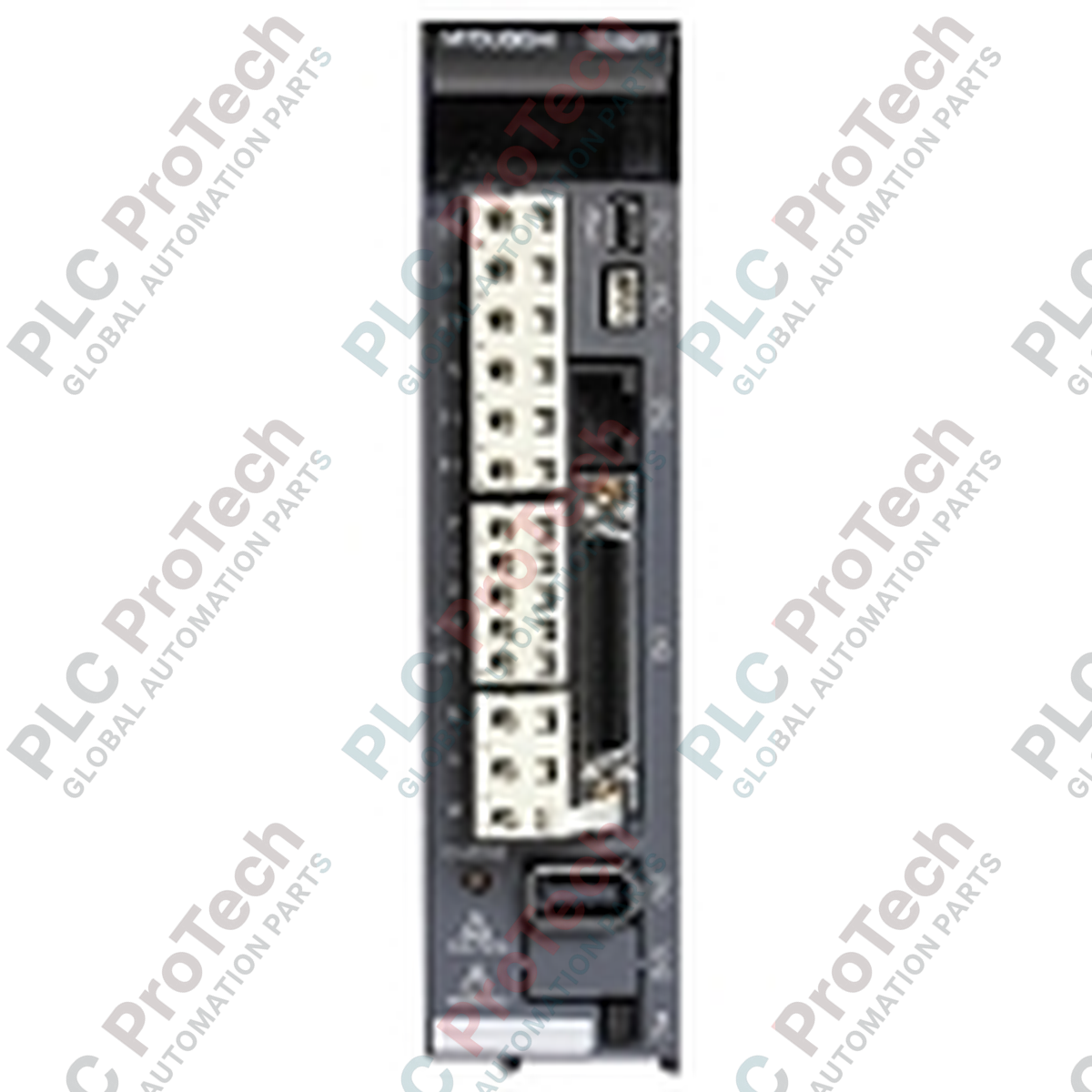
Connections and Interfaces
| Terminal / Connector |
Function / Circuit Assignment |
| CN1A |
SSCNET III Optical Fiber Connector (Upstream/Controller connection) |
| CN1B |
SSCNET III Optical Fiber Connector (Downstream/Next drive connection) |
| CN2 |
Servo Motor Encoder Feedback Interface (18-bit absolute/incremental feedback) |
| CN3 |
External I/O Interface (Limit switches, emergency stop, near-point dog inputs) |
| L1 / L2 / L3 |
Main Power Supply Terminals (3-phase 200-230 VAC input) |
| L11 / L21 |
Control Circuit Power Supply Terminals (Single-phase 200-230 VAC input) |
| U / V / W |
Servo Motor Output Terminals (Output phases to motor windings) |
| P / C / D |
External Regenerative Brake Option Connection Points |
Empirical Engineering Insights
Alternative Models & Compatibility
The MR-J3-500B direct network model operates under SSCNET III protocols and is not directly compatible with SSCNET II controllers or standard analog/pulse train networks (A-type drives). If upgrading an older machine containing an MR-J2S-500B drive, you must replace the standard encoder cables and upgrade the controller to a compatible Q-Series Motion Controller (such as Q172HCPU or QD75MH4) or an L-Series positioning module to support the optical interface.
Application Pitfalls & Engineering Notes
At 5.0 kW rating, this drive generates continuous heat losses of up to 300 Watts under full-load acceleration profiles. When organizing panels, ensure that a minimum of 40 mm free space is maintained above and below the amplifier. If installing multiple amplifiers in a single row, maintain at least 10 mm clearance between drives to prevent mutual thermal loading and premature trigger of thermal protection faults (AL.45 or AL.46).
Commissioning & Wiring Tips
Never exceed the strict 25 mm bend radius limit on the SSCNET III optical fiber cables connecting CN1A and CN1B. Exceeding this limit degrades the light transmission and causes intermittent AL.16 (SSCNET Communication Error) faults. Always use protective plastic covers on unused optical ports to prevent dust or oil-mist infiltration, which permanently degrades the internal receiver optics.
Installation Guidelines
CRITICAL SAFETY WARNING
Before attempting wiring, mechanical installation, or servicing on the power terminal blocks, isolate the main circuit breaker. High-voltage capacitors retain a lethal charge. Verify that the red CHARGE LED located on the physical front of the MR-J3-500B is completely extinguished. Measure the DC bus potential across terminals P(+) and N(-) using a properly rated digital multimeter to verify the voltage has dropped below 50 VDC.
1
Mount the servo amplifier vertically on a flat, rigid metal surface inside a dust-free and oil-mist-free control cabinet with protection class IP54 or higher.
2
Securely connect the primary protective earth (PE) terminal to the cabinet's main copper grounding plate using heavy-gauge braided ground straps to suppress high-frequency noise.
3
Wire the 3-phase AC power input to L1, L2, and L3 using a branch circuit breaker and electromagnetic contactor. Wire control circuit power to L11 and L21 terminals.
4
Connect the dedicated motor output cable to U, V, and W, ensuring phase matching matches the servo motor terminals exactly. Never connect AC input line power directly to motor terminals U, V, or W.
5
Plug the encoder cable into CN2, then plug the optical SSCNET III bus fiber-optic lines into CN1A and CN1B, confirming they click into place. Use standard MR-configurator software for diagnostic configuration.