Description
Engineered for high-performance motion control, the Mitsubishi Electric MR-J4-70B servo amplifier delivers precise position, speed, and torque control within the MELSERVO-J4 ecosystem. Running on an output capacity of 0.75 kW, this 200V class amplifier interfaces natively with motion controllers using the ultra-fast SSCNET III/H synchronous optical network, optimizing cycle times down to 0.222 ms. Its integrated Safe Torque Off (STO) safety function and dynamic vibration suppression filters ensure machine protection and maximum mechanical throughput in demanding factory automation lines.
Key Features
-
SSCNET III/H Command Interface: Optical fiber networking allows high-speed, noise-immune communications with synchronization cycles of 0.222 ms, 0.444 ms, or 0.888 ms.
-
Built-In Safety Functions: Features STO (Safe Torque Off) certified to EN ISO 13849-1 Category 3 PL e and IEC 61508 SIL 3 for rapid motor power de-energization.
-
Dynamic Tuning and Filters: Real-time auto-tuning paired with adaptive vibration suppression, robust filters, and lost motion compensation minimizes settling times and machine resonance.
-
Versatile Power Configurations: Supports single-phase or three-phase input configurations from AC 200V to 240V.
Applications
- Multi-axis positioning systems and high-speed pick-and-place packaging machinery.
- Precision semiconductor handling platforms and rotary indexing tables.
- Automated continuous-path assembly lines requiring synchronized multi-drive networks.
Technical Specifications
| Parameter |
Specification |
| Manufacturer |
Mitsubishi Electric |
| Model Number |
MR-J4-70B |
| Product Series |
MELSERVO-J4 Series |
| Output Rated Power |
0.75 kW |
| Output Rated Voltage |
Three-phase AC 170 V |
| Output Rated Current |
5.8 A |
| Main Circuit Power Input |
Three-phase or Single-phase AC 200 V to 240 V, 50 Hz / 60 Hz |
| Main Circuit Rated Current |
3.8 A |
| Control Circuit Power Input |
Single-phase AC 200 V to 240 V, 50 Hz / 60 Hz |
| Control Circuit Current & Power |
0.2 A / 30 W |
| Command Interface |
SSCNET III/H Interface |
| Control Method |
Sine wave PWM control, current control system |
| Built-in Regenerative Resistor |
20 W |
| Functional Safety |
STO (IEC/EN 61800-5-2), EN ISO 13849-1 Category 3 PL e, SIL 3 |
| IP Protection Class |
IP20 (Natural cooling / open design) |
| Ambient Operating Temperature |
0 degC to 55 degC (no freezing) |
| Weight |
1.4 kg |
| Shipping Weight (Calculated) |
4.0 kg |
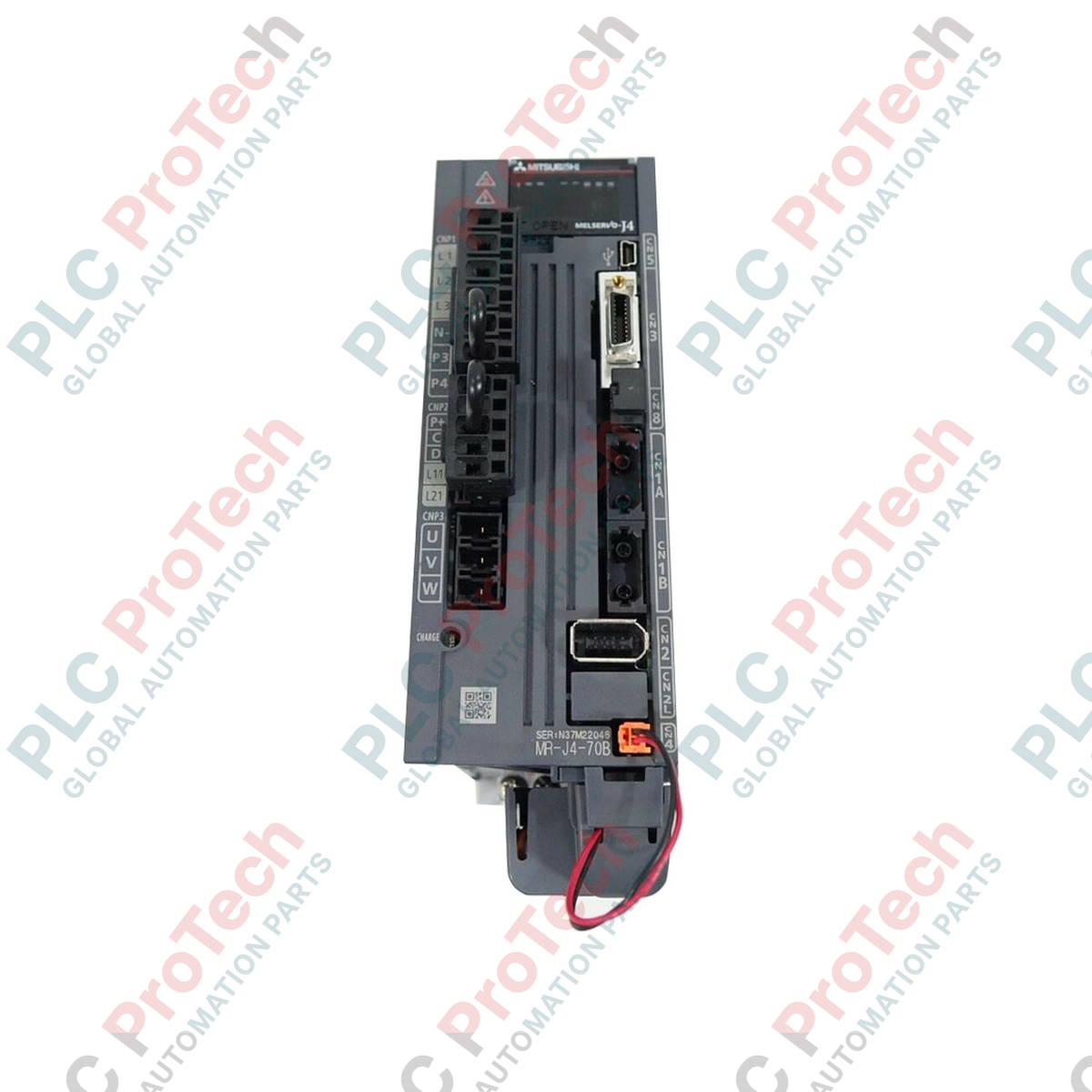
Connections and Interfaces
| Connector / Terminal Block |
Signal / Circuit Assignment |
| L1, L2, L3 |
Main circuit AC power supply input (three-phase or single-phase) |
| L11, L21 |
Control circuit AC power supply input (single-phase) |
| U, V, W |
Servo motor power output (Phase U, Phase V, Phase W) |
| P+, C |
External regenerative resistor connections |
| CN1A / CN1B |
SSCNET III/H optical fiber bus connectors (In / Out) |
| CN2 |
Servo motor encoder feedback interface |
| CN5 |
USB port for PC communication (MR Configurator 2) |
| CN8 |
STO (Safe Torque Off) functional safety connector |
Empirical Engineering Insights
Alternative Models & Compatibility
The MR-J4-70B supports a built-in J3 Compatibility Mode, permitting commissioning in older MR-J3-based SSCNET III system layouts. This enables drop-in physical and functional hardware replacements on mature machine configurations without requiring immediate software or master-controller rewrites. Keep in mind that when operating in J3 compatibility mode, the communication speed defaults to 50 Mbps instead of the native 150 Mbps SSCNET III/H capability.
Application Pitfalls & Engineering Notes
While the MR-J4-70B can operate on single-phase AC input, running the system with highly dynamic load cycles may stress the internal DC bus capacitor bank. Ensure your panel layout preserves a minimum of 10 mm spacing on both sides of the amplifier if multiple units are mounted adjacently, as natural convection cooling relies strictly on unobstructed vertical airflow. For heavy cyclic duty or large inertial mismatches, verify if the internal 20 W regenerative capacity is sufficient; if not, an external regenerative resistor must be added across terminal P+ and C with the internal resistor disconnected.
Commissioning & Wiring Tips
Never touch the polished faces of the SSCNET III/H optical fiber cables. Dust, moisture, or light surface oils will attenuate the optical signal, inducing communication timeouts or erratic cyclic packet dropouts. Ensure the fiber bending radius never goes below 25 mm. Additionally, keep the low-voltage control and feedback lines (CN2/CN8) isolated from power wiring (U/V/W and L1/L2/L3) by routing them through dedicated, grounded metallic conduits.
Installation Guidelines
CRITICAL WARNING:
HAZARDOUS VOLTAGE PRESENT. Disconnect and de-energize all main and control power feeds prior to physical installation or terminal wiring. Allow at least 15 minutes for the internal bus capacitors to discharge. Use a reliable digital voltmeter to confirm the DC bus voltage is zero across P+ and N- terminals before touching the terminals.
1
Mount the amplifier vertically onto a flat, non-flammable back panel using standard mounting hardware to facilitate correct convective airflow through the cooling channels.
2
Establish a solid protective ground connection via the dedicated earth terminals to mitigate electrical noise and prevent shock hazards.
3
Wire the control power (L11/L21) and main circuit input terminals (L1/L2/L3), ensuring appropriate branch-circuit protection fuses or circuit breakers are configured upstream.
4
Connect the encoder cable to CN2 and the SSCNET III/H optical fibers to CN1A/CN1B, verifying that the optical dust protectors are kept clean and stored safely.