Description
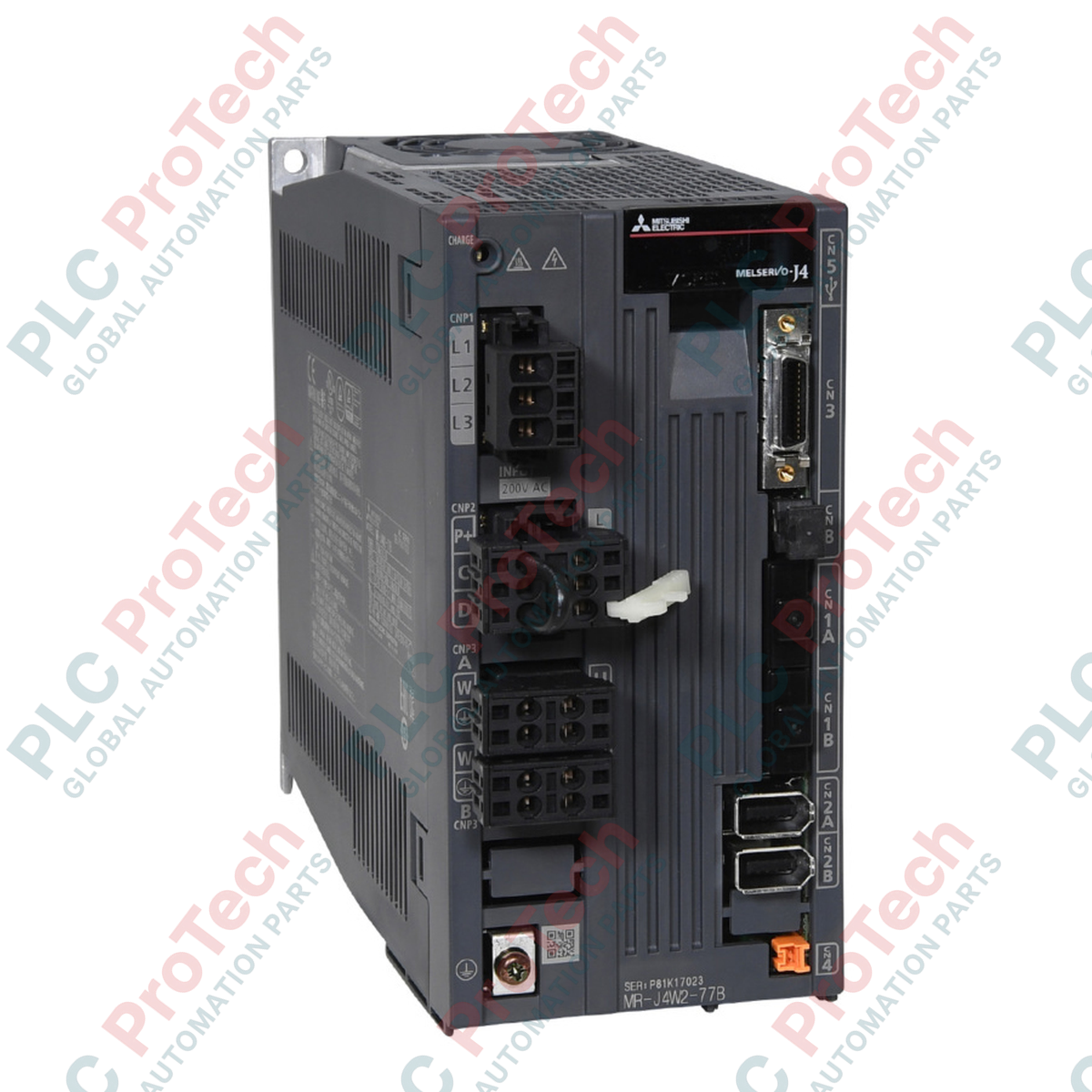
Designed for highly synchronized multi-axis motion control, the Mitsubishi Electric MR-J4W2-77B functions as a high-density, 2-axis AC servo amplifier operating within the MELSERVO-J4 platform. By integrating control circuitry for two independent axes into a single physical unit, this amplifier significantly reduces required electrical panel enclosure footprint and streamlines control bus wiring. It communicates natively via the high-speed SSCNET III/H fiber-optic network, enabling real-time, deterministic motion synchronization with motion controllers and Simple Motion modules. The drive features advanced vibration suppression control II and real-time auto-tuning algorithms to optimize mechanical dynamic response and settle times.
Features
- Dual-axis integration reduces panel layout space requirements compared to two single-axis drives.
- SSCNET III/H optical fiber communication interface delivers high noise immunity and 150 Mbps response rates.
- Compatible with high-resolution rotary and linear motors utilizing 22-bit absolute encoders.
- Integrated Safe Torque Off (STO) function complying with EN ISO 13849-1 Category 3 PL e.
- Real-time adaptive tuning automatically compensates for varying load inertia and mechanical resonance.
Applications
- Synchronized pick-and-place gantry robots and multi-axis Cartesian systems.
- High-speed industrial packaging, filling, and wrapping machinery.
- Precision electronic component insertion and semiconductor assembly lines.
- Automated material handling conveyor feeds and auxiliary machine tool axes.
Technical Specifications
| Parameter |
Specification Value |
| Manufacturer |
Mitsubishi Electric |
| Model Number |
MR-J4W2-77B |
| Series |
MELSERVO-J4 |
| Number of Controlled Axes |
2 Axes (Axis A and Axis B) |
| Rated Output (Per Axis) |
0.75 kW (Axis A) / 0.75 kW (Axis B) |
| Main Circuit Power Input |
3-phase 200 to 240 V AC, 50/60 Hz |
| Control Circuit Power Input |
1-phase 200 to 240 V AC, 50/60 Hz |
| Communication Interface |
SSCNET III/H (High-speed optical network) |
| Control Method |
Sinusoidal PWM control, current systematic control |
| Safety Function |
Safe Torque Off (STO) via CN8 |
| Ambient Operating Temp. |
0 to 55 degC (non-freezing) |
| Product Dimensions |
168 mm (H) x 85 mm (W) x 195 mm (D) |
| Product Net Weight |
2.3 kg |
| Shipping Weight (Calculated) |
3.0 kg |
| Package Dimensions (Calculated) |
250 mm x 150 mm x 220 mm |
| Country of Origin |
Japan |
Connections and Interfaces
| Connector/Terminal |
Functional Allocation |
| CN1A / CN1B |
SSCNET III/H Optical network input/output lines |
| CN2A / CN2B |
Encoder communication interface (Axis A / Axis B) |
| CN3 |
I/O signal connector (External limit switches, proximity sensors) |
| CN8 |
Safe Torque Off (STO) functional circuit connector |
| L1 / L2 / L3 |
Main circuit three-phase AC power input terminal block |
| L11 / L21 |
Control circuit single-phase AC power input terminal block |
| U / V / W (A & B) |
AC Servo motor power output lines for Axis A and Axis B |
Empirical Engineering Insights
Alternative Models & Compatibility
When replacing older MR-J3W series multi-axis drives, please note that physical dimensions and parameter formatting differ. The MR-J4W2-77B requires MR-J4 mode configuration parameters and firmware compatibility with the upstream controller (such as Q-series Motion Controllers or Simple Motion Modules). When migrating existing systems, ensure that SSCNET III/H network configuration tools are updated to support the MR-J4 model profiles.
Application Pitfalls & Engineering Notes
In enclosed panels with limited airflow, the MR-J4W2-77B can experience rapid internal thermal rise. Operating both 0.75 kW axes at high continuous duty cycles simultaneously can trigger a thermal overload alarm (AL 46). Maintaining a 40 mm vertical clearance above/below and a 10 mm lateral clearance is mandatory. If both axes decelerate concurrently under heavy inertial load, verify that the regenerative power does not exceed the internal resistor capacity; install a properly sized external regenerative resistor to prevent overvoltage faults (AL 33).
Commissioning & Wiring Tips
Always use original Mitsubishi MR-CCN1-type optical cables for the CN1A/CN1B ports. Standard fiber-optic cables have a strict minimum bend radius of 25 mm; violating this threshold will lead to optical attenuation, inducing erratic communication dropouts (AL 86.1). Ensure encoder cables (CN2A/CN2B) are physically routed in separate, shielded cable trays away from the motor power cables (U/V/W) to prevent electromagnetic interference from triggering encoder communication errors (AL 1A).
Installation Guidelines
CRITICAL WARNING: Prior to undertaking physical installation or wiring changes, fully isolate the main and control circuit electrical power supplies. After power isolation, wait at least 15 minutes to allow internal high-voltage bus capacitors to discharge. Verify that the physical "CHARGE" LED on the front face of the amplifier is completely dark, and measure the residual DC bus voltage across terminals P+ and N- to verify it is below 45 V before handling terminals.
1
Mount the amplifier vertically on a flat, rigid metallic backplate using the mounting screws. Maintain standard clearance requirements to optimize cooling convection currents.
2
Connect the dedicated functional grounding wire to the amplifier ground terminal and verify connection path back to the system ground busbar.
3
Execute control and encoder wiring, ensuring that the fiber-optic SSCNET connections are fully clicked into position in CN1A/CN1B with the protective caps removed.