Description
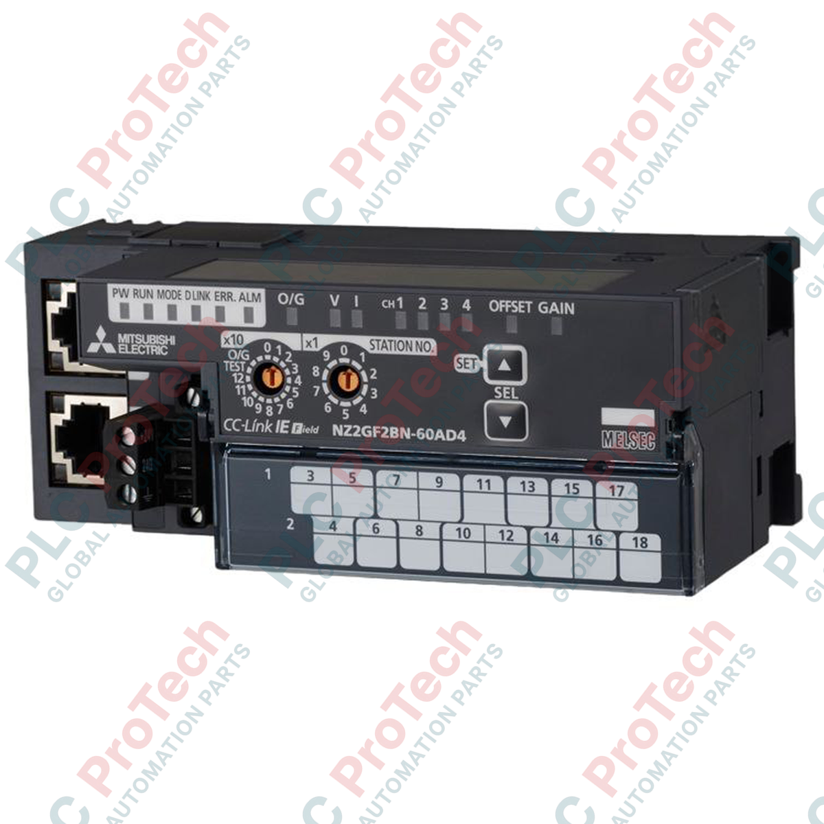
Configured as an analog signal acquisition node for CC-Link IE Field Network architectures, the Mitsubishi Electric NZ2GF2BN-60AD4 provides high-speed, precise analog-to-digital conversion across four independent channels. Designed to integrate into complex industrial automation systems, this module translates external physical voltage and current signals into high-resolution 16-bit signed binary data. Ground loop prevention is maintained via robust galvanic isolation between the communication networks, power circuitry, and internal analog processing loops, ensuring reliable operation in high-noise environments.
Features
-
Four Channels: Support for up to 4 analog input points per module.
-
Configurable Input Modes: Voltage (-10 to 10 VDC) and Current (0 to 20 mADC) configurations selectable per channel.
-
High-Resolution Digital Conversion: Resolves inputs into 16-bit signed binary values ranging from -16384 to 16383.
-
Multi-Barrier Electrical Isolation: Photocoupler isolation for network communications and transformer isolation for power distribution.
-
Removable Terminal Block: Uses an 18-point two-piece terminal block to simplify field wiring and maintenance.
Applications
-
Continuous Process Monitoring: Integrating pressure, temperature, and level transmitters into central control architectures.
-
Water and Wastewater Treatment: Collecting physical sensor metrics from widely dispersed flow meters and chemical analysis systems.
-
Assembly and Assembly Automation: High-speed feedback loops in mechanical stamping, tension control, and robotic positioning systems.
Technical Specifications Table
| Parameter |
Specification Value |
| Manufacturer |
Mitsubishi Electric |
| Model Number |
NZ2GF2BN-60AD4 |
| Network Protocol |
CC-Link IE Field Network |
| Input Channels |
4 channels (4 points / module) |
| Voltage Input Range |
-10 to 10 VDC (Input resistance: 1M ohm) |
| Current Input Range |
0 to 20 mADC (Input resistance: 250 ohm) |
| Digital Resolution |
16-bit signed binary (-16384 to 16383) |
| Comm-to-Analog Isolation |
Photocoupler isolation |
| Power-to-Analog Isolation |
Transformer isolation |
| Channel-to-Channel Isolation |
Non-isolated |
| Withstand Voltage |
500 VAC for 1 minute (between power/comm and analog inputs) |
| Communication Interface |
RJ45 Connector |
| I/O Connections |
18-point two-piece terminal block (M3 screw) |
| Power Supply Terminal |
M2.5 screw terminal block with FG connection |
| Mounting Compatibility |
TH35-7.5Fe, TH35-7.5Al DIN rail (IEC 60715) |
| Unit Weight |
0.31 kg |
| Shipping Weight (Calculated) |
1.50 kg |
Connections and Interfaces
| Terminal / Port |
Interface Type |
Functional Role |
| RJ45 Port |
Industrial Ethernet |
CC-Link IE Field Network physical communication link |
| 18-Point Terminal |
M3 Screw Terminal Block |
Analog input signal connections for channels 1 through 4 |
| Power Terminal |
M2.5 Screw Terminal Block |
External 24 VDC module power supply and Functional Ground (FG) |
Empirical Engineering Insights
Alternative Models & Compatibility
The NZ2GF2BN-60AD4 operates as a standard slave station on CC-Link IE Field Network systems. When replacing legacy serial-based CC-Link analog blocks, ensure that the master station PLC module (such as the QJ71GF11-T2 or equivalent RJ71GP21-SX) supports the appropriate network profile update. Use GX Works2 or GX Works3 parameter configuration utilities to map the system variables correctly.
Application Pitfalls & Engineering Notes
A crucial detail for systems design is that no isolation exists between the individual input channels. Although there is strong galvanic isolation protecting the communication logic and the external main power terminals, the analog channels share a common return pathway. Connecting sensors that have distinct ground potentials to different channels on the same module can create ground loop currents, introducing measuring offsets or causing component damage. If sensor isolation cannot be guaranteed in the field, external signal isolators must be mounted inline.
Commissioning & Wiring Tips
To prevent measurement instability caused by high-frequency electromagnetic noise, always use shielded twisted-pair (STP) cabling for analog signal runs. Terminate the cable shields directly at the FG terminal of the module. Ensure strict adherence to screw terminal torque settings: limit M3 terminal block screws to 0.43 to 0.57 Nm, and M2.5 power supply block screws to 0.5 to 0.6 Nm to avoid structural failure of the connection points.
Installation Guidelines
CRITICAL WARNING: Completely isolate and lock out all power sources feeding the control enclosure before attempting to mount, wire, or remove the module. Failure to de-energize external systems may result in electrical shock, unexpected control system states, or physical hardware failure.
1
Align the rear mounting tab of the module with the top flange of the TH35 standard DIN rail. Push down and swing the unit forward until the bottom lock mechanism clicks firmly into place.
2
Connect the external 24 VDC power lines and the system ground reference wire to the M2.5 terminal block, tightening the terminals to a maximum of 0.6 Nm.
3
Terminate individual analog sensor wires at the removable 18-point terminal block. Securely lock the terminal block assembly back into the module chassis using its integrated side lock.
4
Insert category 5e or higher Ethernet cables into the RJ45 communication ports to establish connections with adjacent nodes on the CC-Link IE Field Network.