Description
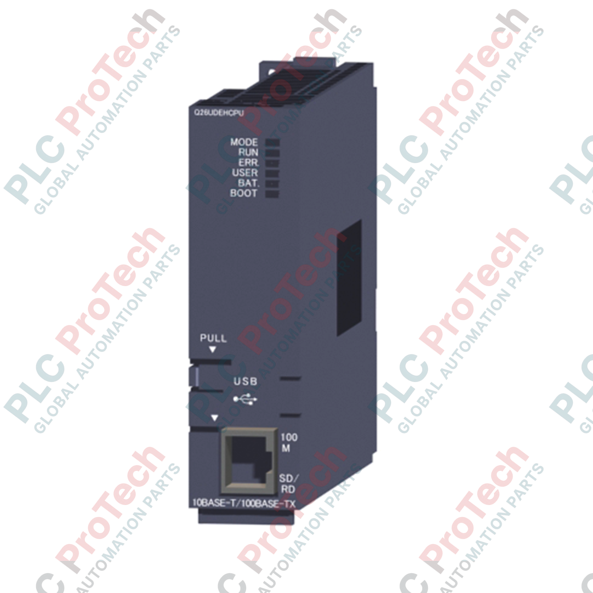
Engineered for high-density, multi-disciplinary industrial control applications, the Mitsubishi Electric Q26UDEHCPU is an industrial-grade central processing unit designed for the MELSEC Q Series automation platform. This module integrates a built-in Ethernet port, enabling high-speed data transmission and seamless communication across factory networks. Featuring a highly optimized execution engine, it handles complex arithmetic, sequence controls, and structured text configurations with exceptional speed. Its physical design fits directly onto standard Q Series base units, making it ideal for systems requiring intensive calculations, multi-CPU coordination, and deep memory capacities.
Key Features
-
High-Speed Processing: Delivers execution speeds of 9.5 ns for basic sequence instructions (LD X0) and 19 ns for data movement operations (MOV D0 D1).
-
Large Memory Footprint: Provides 260 K steps (1040 KB) of program memory, supplemented by 1280 KB of standard RAM and 4096 KB of standard ROM.
-
Built-In Communication: Integrated 100/10 Mbps Ethernet port supporting up to 16 simultaneous socket, MELSOFT, or MC protocol connections, plus 1 dedicated FTP channel.
-
Scalable I/O Capacity: Supports up to 4096 local physical I/O points and an extended logical device range of up to 8192 points.
-
Flexible Programming: Native support for Relay symbol words, Logic symbols, MELSAP 3 (SFC), MELSAP-L, Function Blocks, and Structured Text (ST).
Applications
- High-speed automated packaging and assembly systems.
- Multi-axis synchronization systems involving complex motion control integration.
- Water and wastewater plant control network hubs.
- High-volume data logging, tracking, and MES upstream communication networks.
Technical Specifications
| Specification Parameter |
Value / Rating |
| Manufacturer |
Mitsubishi Electric |
| Model / Article Number |
Q26UDEHCPU (217902) |
| Control Method |
Stored program iteration operation |
| I/O Control Method |
Refresh method (Direct access I/O possible via DX/DY commands) |
| LD Instruction Speed |
9.5 ns |
| Program Capacity |
260 K steps (1040 KB) |
| Standard RAM / ROM |
1280 KB / 4096 KB |
| Ethernet Port Speed |
100/10 Mbps (Full / Half Duplex) |
| Internal Current Consumption (5 VDC) |
0.49 A |
| Operating Temperature Range |
0 to 55 degC |
| Storage Temperature Range |
-25 to 75 degC |
| Relative Humidity |
5 to 95% RH (Non-condensing) |
| Dimensions (H x W x D) |
98 mm x 27.4 mm x 115 mm |
| Net Module Weight |
0.22 kg |
| Shipping Weight (Calculated) |
1.2 kg |
Connections and Interfaces
| Interface Type |
Connector / Format |
Function / Communication Standard |
| Ethernet Port |
RJ45 |
100Base-TX/10Base-T, MC Protocol, FTP Server, Socket Interface |
| USB Port |
Mini-B (USB 2.0 High Speed) |
Direct PC programming connection (GX Works2 / GX Developer) |
Empirical Engineering Insights
Alternative Models & Compatibility
When migrating to the Q26UDEHCPU from legacy non-universal hardware such as the Q25HCPU, engineering configurations must be updated in GX Works2. Universal models use a distinct memory organization structure (Standard RAM Drive 3 is handled differently). Additionally, confirm that any installed extension base units support the high-speed bus interfaces associated with Universal CPUs to prevent bus latency errors.
Application Pitfalls & Engineering Notes
This CPU draws 0.49 A from the 5 VDC internal power rail. When configuring multiple CPUs or high-density network modules on a single rack (e.g., combining this CPU with multiple Ethernet/CC-Link IE units), perform a rigorous current consumption calculation. Standard power supplies like the Q61P may approach their operational limit, requiring an upgrade to high-capacity options such as the Q63P or Q64PN.
Commissioning & Wiring Tips
To maintain maximum throughput on the built-in Ethernet port, avoid routing communication patch cords parallel to motor lines or high-voltage lines. Always use Category 5e Shielded Twisted Pair (STP) cabling. If the Ethernet connection drops or times out under heavy factory floor noise, check that the ground terminal (LG/FG) on the main power supply module is securely tied to a dedicated Class D ground.
Installation Guidelines
CRITICAL WARNING: De-energize all primary and auxiliary power systems feeding the rack prior to installing or removing the CPU module. Failing to completely isolate power can lead to internal circuit degradation or destroy the CPU's memory interface pins.
1
Align the lower hook on the back of the CPU module with the base unit guide hole. Ensure it seats flush against the slot.
2
Push the top of the module firmly onto the base plate until the retaining hook clicks into position. Tighten the top fixing screw (if utilizing standard industrial high-vibration mounts).
3
Insert the backup battery connector into the socket located inside the front compartment cover before applying power to prevent cold-start configuration loss.