Description
Designed for high-speed, high-resolution data acquisition within industrial control architectures, the Omron CJ1W-AD042 provides four high-performance analog input channels in a compact CJ-series form factor. This high-density Special I/O Unit supports multiple voltage and current input ranges with high accuracy, executing A/D conversion in as fast as 20 microseconds per point. Integrated digital isolation between the I/O bus and the controller backplane protects internal CPU logic from field-side electrical noise, making it an excellent choice for demanding process control, loop regulation, and signal monitoring applications.
Key Features
-
Four High-Resolution Channels: Configurable for voltage (1 to 5 V, 0 to 10 V, -5 to 5 V, -10 to 10 V) or current (4 to 20 mA) inputs.
-
Ultra-Fast Conversion Cycle: Converts signals at speeds of 20 microseconds for 1 point, scaling up to 35 microseconds for all 4 points.
-
16-Bit Resolution: High-precision conversion ensures micro-level signal granularity for critical processes.
-
Advanced Signal Processing: Built-in scaling functions (up to plus/minus 32,000), peak value holding, and mean-value buffer processing (up to 512 samples).
-
Disconnection Detection: Automatically flags open-circuit faults on 1 to 5 V and 4 to 20 mA signal runs to prevent process errors.
-
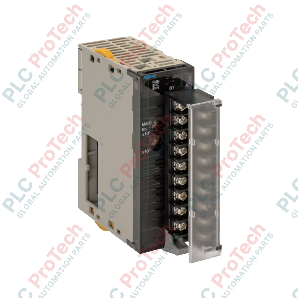
Detachable Terminal Block: Features an 18-point detachable M3 screw terminal block for simplified wiring and fast module replacement.
Applications
- Chemical and petrochemical process loop monitoring
- Pumping station and water treatment pressure tracking
- High-speed manufacturing thermal logging and oven control
- Hydraulic and pneumatic pressure feedback systems
- Factory automation SCADA/HMI telemetry acquisition
Technical Specifications
| Parameter |
Value / Specification |
| Manufacturer |
Omron |
| Module Model |
CJ1W-AD042 |
| Unit Type |
CJ-Series Special I/O Unit |
| Number of Analog Inputs |
4 points |
| Input Signal Ranges (Voltage) |
1 to 5 V, 0 to 10 V, -5 to 5 V, -10 to 10 V |
| Input Signal Ranges (Current) |
4 to 20 mA |
| Maximum Rated Input |
Voltage: plus/minus 15 V | Current: plus/minus 30 mA |
| Input Impedance |
Voltage Input: 1 MOhm min. | Current Input: 250 Ohm (rated) |
| Resolution |
16-bit binary conversion |
| Accuracy (at 25 degC) |
Voltage: plus/minus 0.2% of F.S. | Current: plus/minus 0.4% of F.S. |
| Accuracy (0 to 55 degC) |
Voltage: plus/minus 0.4% of F.S. | Current: plus/minus 0.6% of F.S. |
| A/D Conversion Cycle |
20 us (1 point), 25 us (2 points), 30 us (3 points), 35 us (4 points) |
| Isolation |
Digital isolator between I/O and Controller (No channel-to-channel isolation) |
| Power Consumption |
520 mA max. at 5 VDC |
| Physical Dimensions |
31 mm (W) x 90 mm (H) x 65 mm (D) |
| Net Module Weight |
150 g max. |
| Shipping Weight (Calculated) |
0.35 kg |
| Country of Origin |
Japan |
Empirical Engineering Insights
Alternative Models & Compatibility
The module offers backward compatibility with older CJ-series systems, though Direct Conversion via the AIDC instruction is limited. This direct execution feature is strictly supported on CJ2H-CPU (unit version 1.1 or later) and CJ2M-CPU units. Standard CJ1, NJ501, and CP1H CPU controllers must access analog data via normal cyclic refreshing cycles rather than direct I/O execution instructions.
Application Pitfalls & Engineering Notes
This module uses a shared common configuration; there is no channel-to-channel physical isolation. If field transmitters are powered from different, non-isolated power sources, ground loops can develop, leading to measurement drift or hardware damage. Ensure all current loop transmitters are either loop-powered from a single clean supply or use external signal isolators prior to landing wiring on the terminal block.
Commissioning & Wiring Tips
To minimize high-frequency electromagnetic interference, use shielded twisted-pair (STP) cabling for all signal runs. Connect the cable shields to a single-point system ground plate near the control panel entry, leaving the field end of the shield floating. When wiring, maintain the correct torque on the M3 terminals (0.5 N-m) to prevent signal loss from loose terminations.
Installation Guidelines
CRITICAL WARNING:
Always disconnect and isolate the main system power supply and any external 24 VDC transmitter loops before mounting or extracting the analog module. Installing modules onto an energized backplane can cause transient voltage spikes, resulting in damage to the internal ASIC or the CPU backplane.
1
Align the upper and lower catches of the CJ1W-AD042 module with the mating connectors on the adjacent CJ-series module or backplane unit.
2
Press the module firmly in place until the yellow locking sliders at the top and bottom click into the locked position.
3
Verify that the module address rotary switches (MACH No.) on the front panel are configured to a unique, non-conflicting slot ID.
4
Secure the terminal block, land the shielded wires, and turn on the controller power to execute standard diagnostic self-tests.