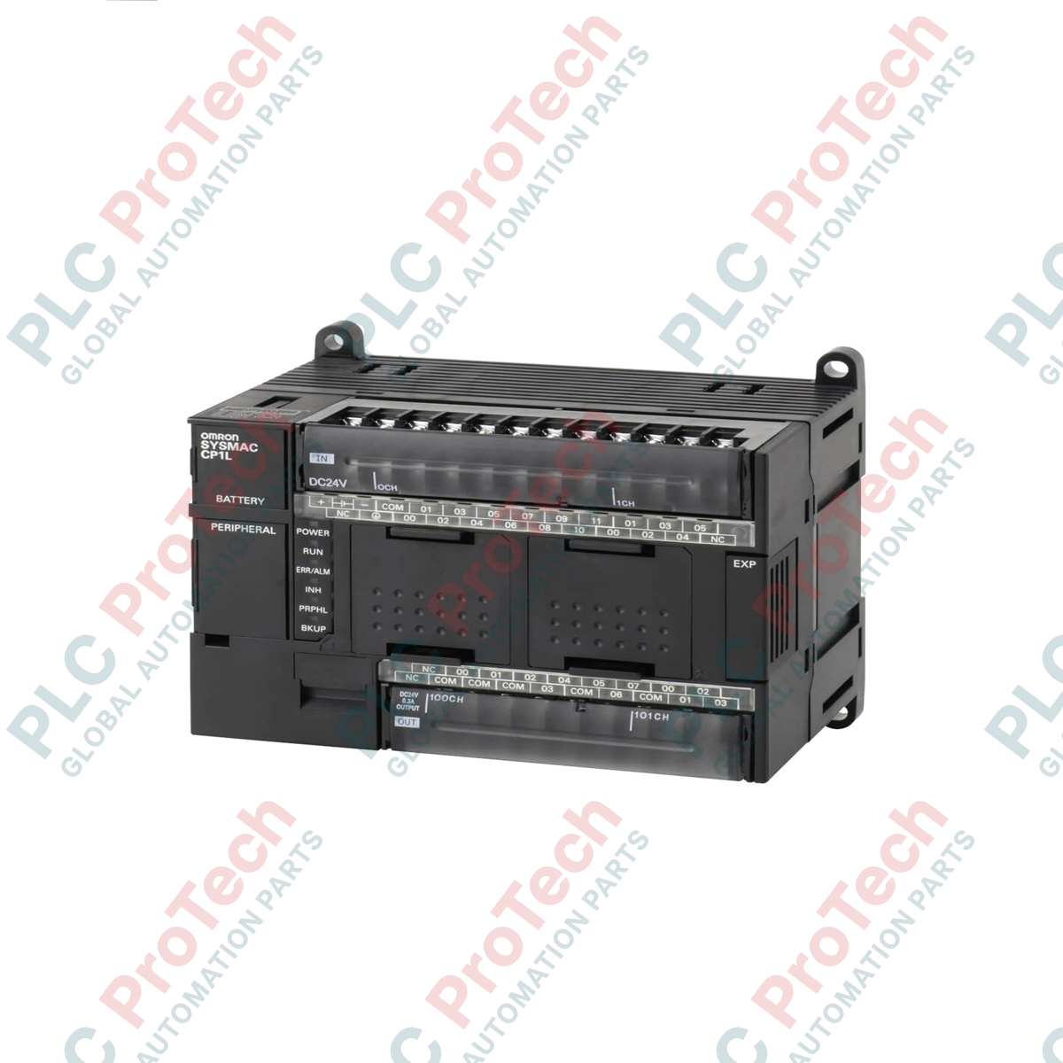
Description
Executing automation routines via a stored program architecture, the Omron CP1L-M30DT-D micro-PLC delivers high-performance processing coupled with integrated Ethernet communications. Designed to fit within compact panel layouts, this CP1L series CPU module utilizes a cyclic scan processing method with immediate I/O refreshing, enabling high-speed response times for complex machinery. The unit supports versatile programming options, allowing engineers to write logic using standardized ladder diagrams and Structured Text (ST) inside function blocks, ensuring seamless integration into modern industrial control architectures.
Features
-
Flexible Programming Environment: Supports up to 128 function block definitions and 256 instances using ladder logic and Structured Text (ST).
-
High-Speed Instruction Execution: Executes basic logical instructions in 0.55 us minimum and special instructions in 4.1 us minimum.
-
Robust Task Management: Manages up to 288 concurrent tasks, structured as 32 cyclic tasks and 256 interrupt tasks.
-
Integrated Analog Channel: Features one onboard analog input (0 to 10 VDC range) with a 1/256 resolution for basic voltage monitoring without auxiliary cards.
-
Expandable Hardware Design: Allows physical expansion of system capacity by connecting up to 3 CP-series expansion or I/O units.
Applications
- Packaging and labeling machinery requiring high-speed execution.
- Material handling systems, conveyor control, and sorting systems.
- Pump control panels and water distribution systems requiring embedded Ethernet telemetry.
- Custom machine-tool automation utilizing interrupt inputs and high-speed counter modes.
Technical Specifications
| Parameter |
Specification |
| Manufacturer |
Omron |
| Model Number |
CP1L-M30DT-D |
| Control Method |
Stored program method |
| I/O Control Method |
Cyclic scan with immediate refreshing |
| Program Capacity |
10K steps |
| Basic Instruction Execution Time |
0.55 us (microseconds) minimum |
| Special Instruction Execution Time |
4.1 us (microseconds) minimum |
| Common Processing Time |
0.4 ms |
| Input Area |
1,600 bits (100 words), CIO 0 to CIO 99 |
| Output Area |
1,600 bits (100 words), CIO 100 to CIO 199 |
| Work Bits |
8,192 bits (512 words), W0 to W511 |
| Holding Area |
8,192 bits (512 words), H0 to H511 |
| Timers |
4,096 timer numbers (T0 to T4095) |
| Interrupt Inputs |
6 inputs (Response time: 0.3 ms) |
| Interrupt Counter Mode |
6 inputs (Response frequency: 5 kHz max), 16-bit up/down |
| Analog Controls |
1 adjustment dial (Setting range: 0 to 255) |
| Onboard Analog Input |
1 input (0 to 10 V, 1/256 resolution, non-isolated) |
| Shipping Weight (Calculated) |
3.00 kg (with protective distribution packaging) |
Empirical Engineering Insights
Alternative Models & Compatibility
The CP1L-M30DT-D requires a nominal 24 VDC power source, as indicated by the trailing "-D" suffix. Care must be taken not to substitute this model directly with the "-A" variant (e.g., CP1L-M30DT-A), which operates on 100-240 VAC mains power. Converting programs from older CP1E systems to CP1L is fully supported within CX-Programmer, though physical terminal configuration differences must be verified prior to downloading the updated task structures.
Application Pitfalls & Engineering Notes
The integrated 0-10 VDC analog input is non-isolated. Deploying this input in environments with high electromagnetic interference (EMI) or severe ground potential differences can corrupt analog measurements. For reliable performance, keep signal cables as short as possible, route them away from variable frequency drive (VFD) output cables, and use high-quality shielded twisted-pair wiring. If isolation is critical, use an external signal isolator before routing to the controller.
Commissioning & Wiring Tips
When configuring the embedded Ethernet interface, ensure the local subnet of your programming workstation matches the PLC default IP allocation. High-speed interrupt inputs (configured for 5 kHz counter operations) require low-capacitance cabling to avoid pulse signal dampening. Ensure the functional ground (FG) terminal is securely tied to a low-impedance earth ground to maximize internal noise filtering performance.
Installation Guidelines
CRITICAL WARNING
Isolate all electrical power sources before attempting mounting, removal, or connection of the CPU module. Confirm that the input voltage matches the specified 24 VDC threshold. Failure to disconnect active field wiring or applying incorrect input voltages can result in permanent hardware failure, circuit damage, or electric shock.
1
Mount the CPU module securely onto standard 35 mm DIN rail or directly to the panel backplate using the mounting screws, ensuring adequate ventilation spacing of at least 50 mm above and below the unit.
2
Connect the external 24 VDC power supply to the dedicated power terminals. Double-check polarity configuration to prevent internal fuse degradation.
3
Ground the PLC functional ground (FG) terminal directly to the panel main earth ground bar using a low-impedance conductor of at least 2.0 mm square.
4
Terminate industrial Ethernet and high-speed I/O field cables, keeping signal lines separate from high-voltage AC lines to minimize signal interference.