Description
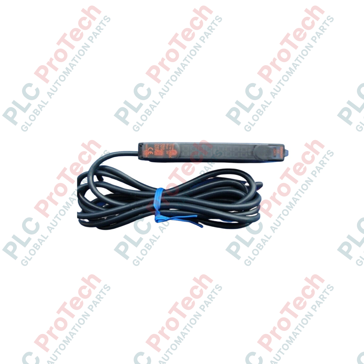
Designed for micro-spot laser sensing and highly detailed parts verification, the Omron E3C-LDA11 functions as a high-precision photoelectric sensor separate digital amplifier. This high-performance DIN-rail mount unit connects to separate Omron laser photoelectric sensor heads, providing dual-channel digital monitoring and high-speed processing directly inside electrical enclosures. By separating the optical head from the processing electronics, the E3C-LDA11 keeps critical evaluation circuitry isolated from demanding field conditions while offering NPN outputs, dual digital displays, and extensive parameter customization via intuitive tactile keys.
Key Features
-
Dual Digital Display: Simultaneous real-time readout of current incident light levels (red display) and user-defined threshold levels (green display).
-
High-Speed Response: Selectable response times ranging from super-high-speed (for fast manufacturing lines) to long-distance modes.
-
Mutual Interference Prevention: Integrated protection circuitry prevents optical cross-talk when multiple sensor heads are mounted in close proximity.
-
NPN Open Collector: Dual outputs configured for NPN switching logic, suitable for seamless integration with standard PLC input cards.
-
DIN Rail Mounting: Slim, space-saving design permits side-by-side array installations inside control panels.
Industrial Applications
-
Semiconductor Wafer Processing: Precision detection of wafer edges and carrier cassette positioning.
-
Electronic Assembly Lines: Verification of ultra-small SMD components, chip placement, and connector pin alignment.
-
High-Speed Packaging: Detection of packaging film registration marks and product presence verification inside cartoning systems.
-
Automated Tooling & Robtotics: Precise monitoring of micro-drill presence and robotic gripper end-effector alignments.
Technical Specifications
| Parameter |
Specification |
| Manufacturer |
Omron |
| Model Number |
E3C-LDA11 |
| Product Type |
Photoelectric Sensor Separate Digital Amplifier |
| Supply Voltage |
12 to 24 VDC plus/minus 10% (ripple p-p 10% max.) |
| Current Consumption |
45 mA maximum |
| Control Output |
NPN open collector, load current 50 mA max., residual voltage 1 V max. |
| Light Source Capability |
Compatible with E3C-LD series sensor heads (Red Laser) |
| Protection Circuits |
Power supply reverse polarity protection, output short-circuit protection, mutual interference prevention |
| Ingress Protection Rating |
IP50 (IEC 60529) |
| Ambient Operating Temperature |
-10 to +55 degC (no icing or condensation) |
| Connection Method |
Pre-wired cable (standard length 2 meters) |
| Net Weight |
0.1 kg |
| Shipping Weight (Calculated) |
1.0 kg (with protective transport packaging) |
Wiring Connection and Interface Assignment
| Wire Color |
Signal Name |
Function / Description |
| Brown |
+V (VCC) |
Power Supply Input: 12 to 24 VDC |
| Blue |
0 V (GND) |
Power Supply Ground / Common Reference |
| Black |
OUT 1 |
NPN Open Collector Control Output (Main detection signal) |
| White |
OUT 2 / INPUT |
NPN Output 2 (Self-diagnostic/Alarm) or External Input line (Configurable) |
Empirical Engineering Insights
Alternative Models & Compatibility
The E3C-LDA11 utilizes NPN output logic. If your system architecture uses PNP (typically standard in European automotive and material handling panels), you must specify model E3C-LDA41 instead. Do not mix NPN and PNP models in the same localized terminal bank without signal conversion modules. This amplifier is specifically calibrated to operate with the E3C-LD series laser head units; attempting to connect older, non-laser photoelectric heads may damage the physical emitter interface or throw sensor-mismatch error codes.
Application Pitfalls & Engineering Notes
When packing multiple E3C-LDA11 units together on a single DIN rail, heat dissipation must be taken into account. Although the nominal operating range extends to +55 degC, side-by-side array installations of more than five units under continuous load can lead to thermal accumulation, shifting internal clock frequencies and altering precise threshold values. We recommend inserting 5mm spacer plates between blocks of five units to preserve baseline thermal equilibrium.
Commissioning & Wiring Tips
During commissioning, verify that the laser head's connection cable is securely locked into the amplifier side-port prior to supplying 24VDC control voltage. Hot-plugging the sensor head can induce transient electrical spikes that degrade the laser diode. Ground the DIN rail thoroughly to mitigate electromagnetic interference, which can otherwise trigger false microsecond-level detection signals in high-speed sensing modes.
Installation Guidelines
CRITICAL WARNING: SAFETY FIRST
Disconnect all electrical power sources before handling, wiring, or mounting the sensor amplifier. Verify that no residual power remains in the control panel to prevent accidental short circuits, component destruction, and potential injury. Do not look directly into the laser beam emitted by the connected sensor head.
1
Mount the E3C-LDA11 onto standard 35mm symmetric DIN rail. Ensure the back clip latches firmly in place.
2
Open the outer protective cover and insert the specialized optical sensor head connector until it clicks into the dedicated socket.
3
Route the 4-wire pre-wired cable away from major AC power lines or variable frequency drives (VFDs) to limit noise. Connect the wires strictly according to the schematic table.
4
Apply 12-24 VDC power and execute the target teaching protocol using the faceplate buttons to establish operational signal thresholds.