Description
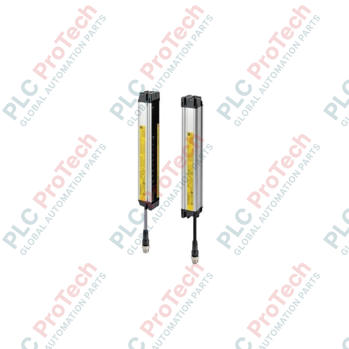
Providing reliable hand and arm detection in high-risk automated areas, the Omron F3SJ-B0465P25 safety light curtain establishes an invisible optical safeguarding field to prevent hazardous industrial contact. Designed as a Type 4 safety sensor, this robust light barrier features a 465 mm protective height and utilizes 22 infrared beams spaced at a 20 mm pitch. Operating on a stable 24 VDC power supply, the unit provides dual PNP outputs (OSSDs) that interface seamlessly with safety monitoring relays and safety controllers. Its integrated construction and high environmental resistance make it a reliable choice for manufacturing lines, robotic cells, and material handling systems requiring continuous operation and safety compliance.
Features
-
High-Performance Safeguarding: Type 4 safety light curtain compliant with global safety standards for hand and arm protection.
-
Streamlined Design: Compact housing simplifies mechanical integration within tight machine envelopes.
-
Long Operating Range: Ensures stable detection over distances ranging from 0.2 to 7 meters.
-
Robust Environmental Design: IP65 protection rating safeguards internal optical elements against dust and low-pressure water jets.
-
Dual PNP Outputs: Facilitates redundant safety integration with safety PLCs and control relays.
Applications
-
Robotic Workcells: Establishes protective optical perimeters around articulated robot arms and end-effectors.
-
Packaging and Assembly Lines: Safeguards access points where personnel interact with moving conveying or sorting mechanisms.
-
Metal Stamping and Pressing: Prevents operator entry into dangerous press zones during cycle operation.
-
Material Handling: Limits physical entry to automated storage, palletizing, and retrieval areas.
Technical Specifications
| Parameter |
Specification |
| Manufacturer |
Omron |
| Model Number |
F3SJ-B0465P25 |
| Product Type |
Safety Light Curtain |
| Sensor Type |
Type 4 |
| Detection Capability |
25 mm diameter (Hand protection) |
| Protective Height |
465 mm |
| Number of Beams |
22 |
| Beam Gap (Pitch) |
20 mm |
| Operating Range |
0.2 to 7.0 m |
| Output Type |
Dual PNP outputs (OSSDs) |
| Supply Voltage (Vs) |
24 VDC +/-20% (SELV/PELV) |
| Current Consumption (No Load) |
Emitter: 52 mA max. / Receiver: 45 mA max. |
| Light Source Wavelength |
Infrared LED (870 nm) |
| Degree of Protection |
IP65 |
| Net Weight |
1.8 kg |
| Shipping Weight (Calculated) |
3.0 kg |
| Package Dimensions (Calculated) |
600 x 150 x 150 mm |
Alternative Models & Compatibility
The F3SJ-B (Basic) series can easily replace legacy Omron F3SJ-E (Easy) curtains where advanced feedback loops or longer sensing ranges are required, and can be interchanged with F3SJ-A (Advanced) series systems if highly customized blanking or muting functions are not needed. Ensure that your safety controller parameters are verified, as different suffixes within the F3SJ family specify output logic (PNP vs NPN) and cabling configurations.
Application Pitfalls & Engineering Notes
When mounting units close together, physical alignment and optical cross-talk must be managed. If installing multiple F3SJ-B systems back-to-back, physically alternate the emitter and receiver directions to avoid mutual interference. Avoid exposing the receiver face to direct sunlight, high-frequency fluorescent lights, or intense reflective surfaces, which can trigger intermittent lockouts or false optical status signals.
Commissioning & Wiring Tips
Always run OSSD1 and OSSD2 safety outputs in separate shielded, grounded cables to prevent capacitive coupling and potential short-circuits to the 24 VDC line, which would trigger a fault. Use the integrated LED indicators on the receiver to fine-tune the optical alignment; when the top and bottom beams are aligned correctly, the indicators change from red to solid green, ensuring stable and robust optical coupling.
Installation Guidelines
CRITICAL WARNING: Prior to starting any physical installation, mounting, or wiring modifications, verify that the primary power source to the machinery and the light curtain is completely de-energized. Locked-out and tagged-out procedures must be strictly enforced. Failure to discharge residual capacitance or verify a zero-energy state can result in severe equipment damage, electrical shock, or involuntary machinery startup.
1
Mounting Alignment: Securely mount the emitter and receiver on rigid, vibration-free surfaces at equal heights. Ensure that the optical faces are parallel and directly facing each other.
2
Wiring Connection: Connect the emitter and receiver utilizing the appropriate industrial M12 cabling, ensuring safety output wires (OSSD1/OSSD2) are routed directly to your safety relay or safety PLC input terminals.
3
System Testing: Energize the system and perform a walk-through test using an approved test piece of the specified 25 mm diameter to confirm that breaking any beam along the entire protective height instantly trips the safety outputs.