Description
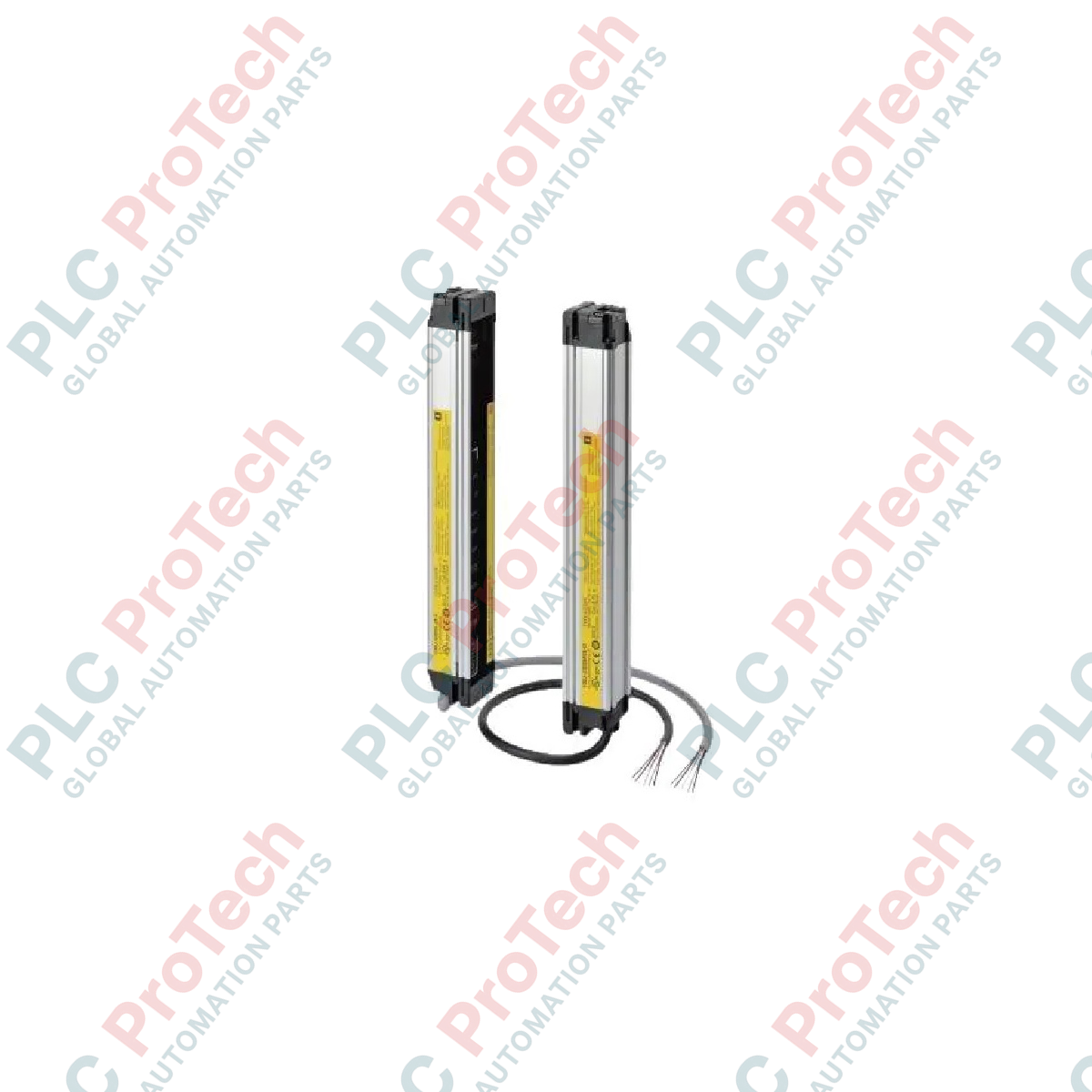
Designed to provide robust optoelectronic safeguarding in automated industrial workspaces, the Omron F3SJ-E0225N25 functions as a Type 4 safety light curtain engineered specifically for hand detection. This compact protective barrier integrates seamlessly into existing safety control systems, utilizing an infrared optical array to monitor hazardous zones and immediately trigger machine stops upon interruption. Utilizing an NPN solid-state output configuration, the Omron F3SJ-E0225N25 simplifies field wiring while meeting stringent European and international functional safety standards for machinery guarding.
Features
-
Robust Detection Capability: 25 mm beam gap allows reliable detection of hands and larger objects passing through the detection field.
-
Long-Range Performance: Operating distance spans from 0.2 m up to 7.0 m, catering to versatile machine footprints.
-
NPN Output Logic: Designed for integration with control systems requiring active-low switching architecture.
-
Simplified Wiring: Part of the Omron "Easy" (E-type) series, minimizing installation complexity and reducing commissioning overhead.
-
Status Diagnostics: Visible LED indicators on both emitter and receiver elements assist in quick alignment and diagnostic checks.
Applications
- Robotic work cell perimeter monitoring and entry gates.
- Pick-and-place packaging machine safety guarding.
- Automated assembly line conveyor access point protection.
- Automated guided vehicle (AGV) path obstruction detection.
Technical Specifications Table
| Manufacturer |
Omron |
| Model / Article Number |
F3SJ-E0225N25 |
| Safety Category |
Type 4 (IEC 61496-1) |
| Output Type |
NPN semiconductor outputs (x2) |
| Protective Height |
225 mm |
| Number of Beams |
10 |
| Detection Capability |
25 mm diameter |
| Operating Range |
0.2 m to 7.0 m |
| Supply Voltage |
24 VDC +/- 20% (SELV/PELV ripple p-p 10% max) |
| Light Source |
Infrared LED (wavelength: 870 nm) |
| Enclosure Protection Rating |
IP65 (IEC 60529) |
| Device Weight |
1.1 kg |
| Shipping Weight (Calculated) |
2.0 kg |
Empirical Engineering Insights
Alternative Models & Compatibility
The F3SJ-E (Easy) series features simplified connection protocols and does not support complex configurations like blanking or muting, which are native to the F3SJ-A (Advanced) or F3SJ-B (Basic) series. When replacing an existing light curtain, verify that your safety PLC or safety relay module logic expects NPN switching logic, as PNP variations (F3SJ-E0225P25) cannot be interchanged without wiring modification.
Application Pitfalls & Engineering Notes
Ensure that highly reflective surfaces (such as polished stainless steel or glossy safety panels) are kept outside the optical path's minimum reflective distance boundary. Failing to maintain this clearance can cause the receiver to process reflected light rather than direct beams, potentially failing to register a safety breach. Always compute safety distance margins based on standard EN ISO 13855 formulas before final mechanical mounting.
Commissioning & Wiring Tips
When routing cables for the emitter and receiver, keep them isolated from high-voltage AC motor lines, variable frequency drives (VFDs), and heavy inductive loads to prevent electromagnetic interference. Standard SELV/PELV power supplies must be common-grounded to the system chassis to ensure reliable functioning of the NPN output detection circuit.
Installation Guidelines
CRITICAL WARNING: Prior to starting any physical installation, electrical wiring, or maintenance procedures, ensure all electrical energy sources to the target machinery are fully de-energized, locked out, and verified dead. Failure to isolate these power paths can lead to unexpected machine startup, severe shock, or fatal industrial injury.
1
Position and secure the mounting brackets on a stable structural frame, ensuring both emitter and receiver elements are perfectly aligned on the horizontal and vertical planes.
2
Route the connection cables securely using protective conduit to prevent physical wear, making certain to isolate the routing from power lines.
3
Terminate the NPN outputs and 24 VDC power lines into your designated safety control relay or safety PLC input terminals in accordance with standard schematic procedures.
4
Apply system power and verify the status LEDs on both units; fine-tune the alignment until the green status indicators illuminate continuously, indicating an uninterrupted optical path.