Description
Integrating legacy serial instruments and third-party peripherals into modern Sysmac architectures is streamlined using the Omron NX-CIF210. This high-density serial communications interface unit expands the capabilities of NX-series I/O systems and NJ/NX CPU racks by adding two independent, non-isolated RS-232C ports. Operating primarily under "No-protocol" transmission modes, it allows raw ASCII or hexadecimal data exchange with devices such as barcode readers, weight scales, and industrial sensors, without requiring complex protocol stacks.
Features
-
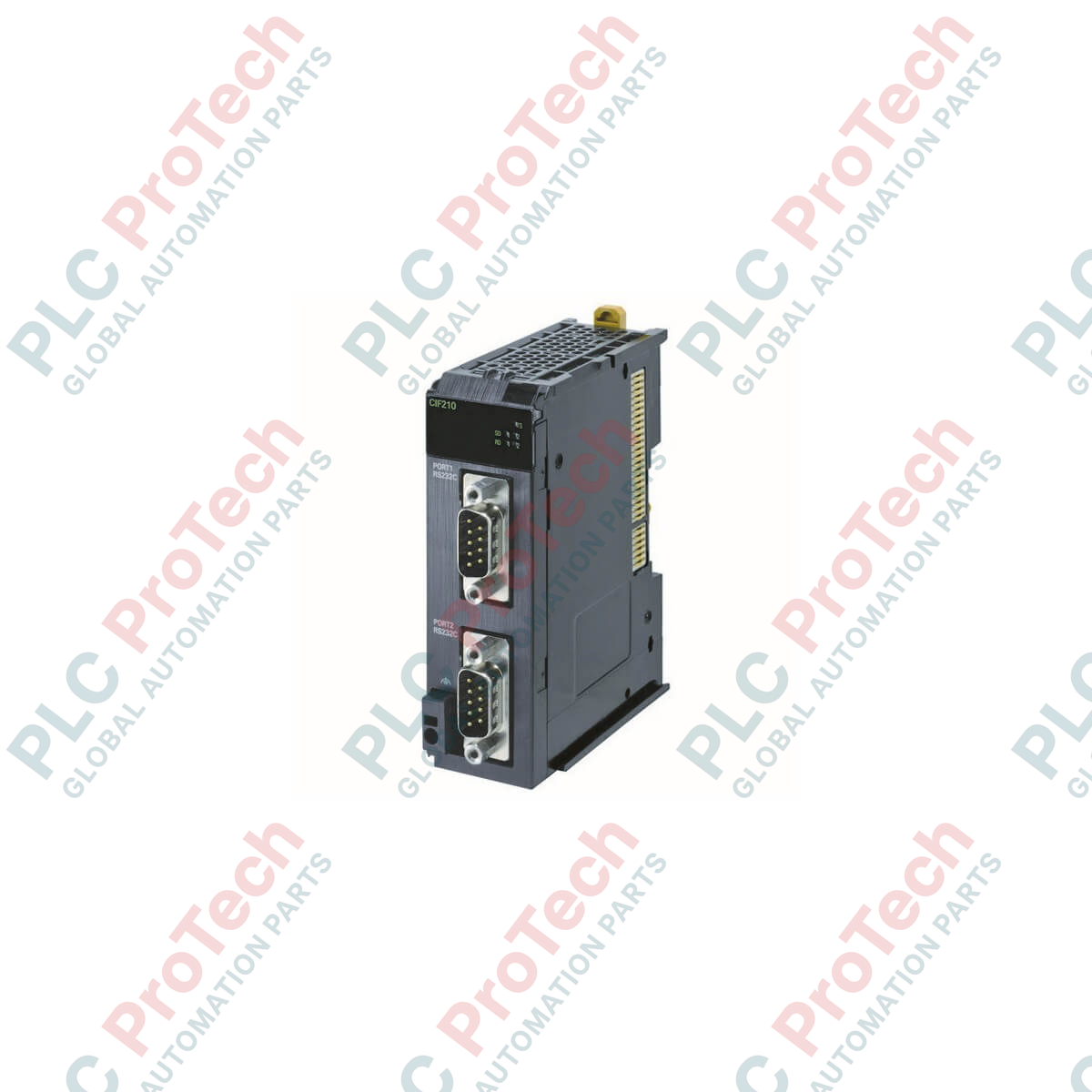
Dual-Channel Interface: Equipped with two independent RS-232C communication channels utilizing industry-standard D-Sub 9-pin connectors.
-
Flexible Architecture: Mounts seamlessly to NX-series EtherCAT Coupler Units or directly to compatible NX-series Controller Units.
-
High-Speed Bus Sync: Synchronizes serial data buffering with the internal NX-bus cycle for deterministic control execution.
-
Simplified Configuration: Full setup, baud rate adjustment, and diagnostics integrated directly within the Sysmac Studio software environment.
-
Space-Saving Profile: Compact 30 mm housing width reduces overall footprint inside electrical control panels.
Applications
- Connecting factory-floor barcode scanners and handheld RFID readers.
- Interfacing with precision electronic weigh scales and laboratory instruments.
- Establishing serial point-to-point links with legacy HMIs or display panels.
- Data acquisition from temperature controllers and flow meters via serial command sets.
Technical Specifications
| Specification Parameter |
Value / Detail |
| Manufacturer |
Omron |
| Model Number |
NX-CIF210 |
| Product Series |
NX Series I/O System |
| Module Type |
Serial Communications Interface Unit |
| Number of Ports |
2 |
| Physical Interface |
RS-232C (D-Sub 9-pin Female connectors) |
| Communications Protocol |
No-protocol (Host Link support available depending on master controller configuration) |
| Isolation Method |
No isolation (between ports or internal bus circuits) |
| Product Dimensions |
100 mm (H) x 30 mm (W) x 71 mm (D) |
| Net Weight |
0.091 kg (91 grams) |
| Shipping Weight (Calculated) |
1.50 kg (including commercial protective packaging) |
| Country of Origin |
Japan |
Connections and Interfaces
The unit features two front-facing 9-pin D-sub connectors. The pin assignment conforms to standard RS-232C signal layouts:
| Pin Number |
Signal Abbreviation |
Signal Direction |
Description |
| 1 |
CD |
Input |
Carrier Detect |
| 2 |
RDD (RXD) |
Input |
Receive Data |
| 3 |
SDR (TXD) |
Output |
Transmit Data |
| 4 |
DTR |
Output |
Data Terminal Ready |
| 5 |
SG |
-- |
Signal Ground |
| 6 |
DSR |
Input |
Data Set Ready |
| 7 |
RTS |
Output |
Request to Send |
| 8 |
CTS |
Input |
Clear to Send |
| 9 |
RI |
Input |
Ring Indicator |
Alternative Models & Compatibility
For installations requiring screwless push-in clamping terminals instead of D-Sub 9 connectors, the NX-CIF101 provides a single-channel RS-232C port. If RS-422A or RS-485 serial communication is required, the NX-CIF105 should be selected instead. Confirm firmware compatibility inside Sysmac Studio when mixing older unit revisions with newer NX1P2 or NX102 series controllers.
Application Pitfalls & Engineering Notes
Because this module is non-isolated, ensure that both the NX-series system ground and the ground of the connected RS-232C device are at identical electrical potentials. Significant potential differences can cause ground loop currents, resulting in communication errors or permanent damage to the module's transceiver IC. To preserve signal integrity, the maximum allowable cable length for RS-232C connections is strictly 15 meters.
Commissioning & Wiring Tips
When assembling custom RS-232C cables, always connect the cable shield to the metal hood of the D-Sub connector on the NX-CIF210 end only. This path routes high-frequency noise directly to the DIN rail ground system. If communication failures occur during startup, use the Sysmac Studio monitoring tools to verify if the frame length matches the buffer configuration set in the memory allocation table.
Installation Guidelines
CRITICAL WARNING
Always completely isolate the 24 VDC control power supply to the NX-bus and any connected serial devices before mounting, sliding, or unmounting the unit. Failure to fully de-energize the assembly can cause backplane communication lockouts or damage the internal bus contacts.
1
Align the interlocking guide rails of the NX-CIF210 with the adjacent NX unit on the DIN rail and slide the module together until the side lock click is engaged.
2
Hook the bottom mounting latch to the DIN rail and apply light upward pressure until the module locks firmly into place.
3
Insert the D-Sub 9-pin connector cables and hand-tighten the retaining screws to prevent loose contacts and maintain a continuous shield path.