Description
High-speed position tracking within EtherCAT and PLC architectures is executed by the Omron NX-EC0112, a high-performance NX-series position interface module. This module is engineered to provide precise incremental encoder feedback directly to the control loop, eliminating processing latency. By utilizing a robust 16-point screwless push-in clamping terminal block, the device guarantees secure, vibration-resistant electrical connections in harsh industrial environments. It supports highly flexible integration, allowing control systems to adapt dynamically through multiple synchronization and task-prioritized refreshing methods.
Features
-
Single-Channel Encoder Tracking: Supports comprehensive phase monitoring with dedicated inputs for Phases A, B, and Z.
-
Auxiliary Control Inputs: Integrates three 24 VDC voltage inputs for external positioning markers or latch signals.
-
Advanced Refreshing Schemes: Supports Free-Run, Synchronous, and Task Period Prioritized refreshing to match complex application timing requirements.
-
Tool-Free Installation: Push-in clamping mechanism simplifies field wiring and reduces maintenance downtime.
-
Compact Design Profile: Space-efficient form factor allows dense configuration on standard DIN rails.
Applications
- Rotary and linear position tracking in automated packaging and wrapping machinery.
- High-speed cut-to-length systems requiring real-time encoder pulse synchronization.
- Conveyor sorting lines and material handling gantry position feedback loops.
Technical Specifications
| Specification Parameter |
Value / Rating |
| Manufacturer |
Omron |
| Model Number |
NX-EC0112 |
| Series |
NX-series Position Interface |
| Number of Channels |
1 Channel |
| Input Signals |
Counter (Phases A, B, Z) + 3 External Inputs |
| Input Form |
Voltage Input (24 VDC) |
| Counting Unit |
Pulses |
| I/O Refreshing Methods |
Free-Run, Synchronous, Task Period Prioritized |
| Connection Interface |
Screwless Clamping Terminal Block (16 Terminals) |
| Device Weight |
70 g maximum |
| Shipping Weight (Calculated) |
1.0 kg |
Empirical Engineering Insights
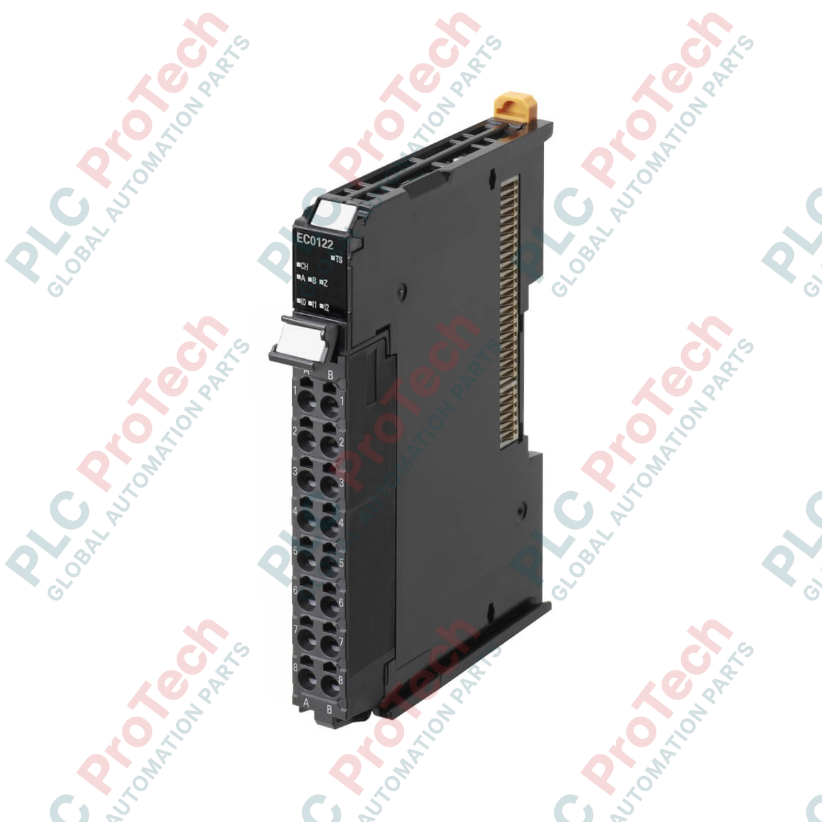
Alternative Models & Compatibility: The unit serves as the 24 VDC single-ended voltage input version in the position interface lineup. If your system design switches to line driver encoder types (differential interfaces), you must migrate to the differential alternative (such as the NX-EC0122) to ensure hardware signal matching. Ensure your Sysmac Studio software matches the firmware revision of the NX-series CPU to prevent diagnostic communications faults upon first power-on.
Application Pitfalls & Engineering Notes: Because the encoder inputs operate on 24 VDC voltage logic, they are more susceptible to electromagnetic noise than differential line drivers. Avoid routing the encoder input cables in the same conduit or cable tray as high-current motor drive output lines or AC power distribution networks to prevent positioning jitter or phantom counts.
Commissioning & Wiring Tips: Utilize high-quality shielded twisted-pair (STP) cabling for Phases A, B, and Z. Connect the shield line exclusively to the functional ground terminal of the NX-series backplane assembly to provide an effective path for high-frequency noise mitigation.
Installation Guidelines
CRITICAL WARNING: Prior to attempting installation, wiring, or maintenance of this module, ensure that all main electrical panels, unit power supplies, and external 24 VDC I/O power lines are completely de-energized. Failure to strictly follow this safety protocol can cause internal dielectric breakdown of the sensor interface circuits or unintended machine movement.
1
Align the unit's guides with the DIN rail and slide the module smoothly until the slide locking mechanism snaps securely onto the rail track.
2
Strip individual field wiring conductors to the manufacturer-specified length (8 to 10 mm) without twisting or tinning the bare wire ends.
3
Insert the solid conductor or standard ferrule directly into the screwless terminal port. To remove or insert stranded wires without ferrules, press the orange release button with a flat-blade driver.
4
Verify that the field sensor shield is securely terminated to the ground bar to minimize signal interference.