Description
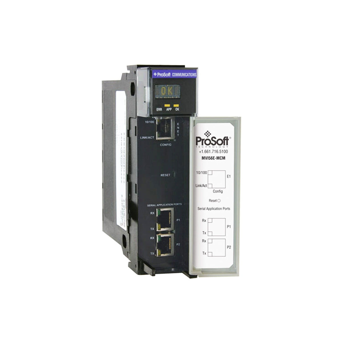
Providing seamless serial connectivity within Allen-Bradley ControlLogix control architectures, the ProSoft MVI56E-MCMXT functions as an industrial-grade Modbus Master/Slave interface module designed specifically for extreme environments. This extended-temperature module permits Allen-Bradley ControlLogix processors to interface directly with diverse Modbus serial field devices, including flow computers, power monitors, variable frequency drives, and remote terminal units (RTUs). Equipped with conformal coating and robust electrical isolation, it delivers continuous protocol translation in demanding industrial operations where standard communication cards are prone to environmental failure.
Features
-
Dual Independent Ports: Two individually configurable serial ports capable of operating concurrently as Modbus Master and/or Modbus Slave nodes.
-
Extended Environmental Tolerance: Conformal-coated circuitry engineered to withstand corrosive atmospheres, moisture, and extreme temperature variations.
-
Rockwell Automation Integration: Integrates directly into the 1756 ControlLogix chassis, utilizing custom Add-On Instructions (AOI) and Add-On Profiles (AOP) for simplified RSLogix 5000 and Studio 5000 programming.
-
Advanced Diagnostics: Dedicated 10/100 Mbps Ethernet port (CFG) provides diagnostic visualization, parameter adjustments, and firmware updates via the ProSoft Configuration Builder (PCB) utility.
-
Protocol Versatility: Native support for Modbus RTU and Modbus ASCII formats with configurable parity, baud rates, stop bits, and RTS timing parameters.
Applications
-
Oil and Gas Processing: Interfacing custody transfer flow meters, gas chromatographs, and tank gauging systems to a central ControlLogix processor.
-
Water and Wastewater Treatment: Integration of scattered chemical dosing pumps, flow sensors, and remote RTUs over long-distance serial topologies.
-
Power Utility Systems: Consolidating data from protective relays, power quality monitors, and generator control panels.
-
Chemical Manufacturing: Safe operation in corrosive process environments where standard non-conformal coated communication cards risk premature corrosion failure.
Technical Specifications
| Specification Parameter |
Value / Detail |
| Manufacturer |
ProSoft Technology |
| Model Number |
MVI56E-MCMXT |
| Module Series |
MVI56E Enhanced Modbus Serial |
| Platform Compatibility |
Allen-Bradley ControlLogix (1756 Chassis) |
| Modbus Protocol Modes |
Modbus RTU (Binary) with CRC-16, Modbus ASCII with LRC checking |
| Supported Baud Rates |
110 to 115,200 baud |
| Data/Stop Bits & Parity |
Stop bits: 1 or 2; Parity: None, Even, Odd |
| RTS Timing Delays |
0 to 65,535 milliseconds |
| Conformal Coating |
Yes (Extended environmental protection) |
| Operating Temperature |
-25 degC to 70 degC (-13 degF to 158 degF) |
| Backplane Current Draw |
800 mA @ 5 VDC, 3 mA @ 24 VDC |
| Country of Origin |
United States |
| Shipping Weight (Calculated) |
2.0 kg (approx. 4.4 lbs) |
| Package Dimensions (Calculated) |
250 mm x 150 mm x 60 mm |
Connections and Interfaces
| Port Reference |
Physical Interface |
Electrical/Functional Assignment |
| PRT1 (Port 1) |
RJ45 (DB9 adapter cable included) |
Modbus Master/Slave Serial Port (RS-232, RS-422, or RS-485 configurable) |
| PRT2 (Port 2) |
RJ45 (DB9 adapter cable included) |
Modbus Master/Slave Serial Port (RS-232, RS-422, or RS-485 configurable) |
| CFG (Configuration) |
RJ45 10/100 Mbps Ethernet |
Dedicated configuration, system utility upload/download, and remote diagnostics |
Alternative Models & Compatibility
The MVI56E-MCMXT is the ruggedized, conformal-coated alternative to the standard MVI56E-MCM module. It is backward-compatible with legacy MVI56-MCM data structures, allowing it to serve as a direct physical and logical drop-in replacement in older ControlLogix systems. This compatibility prevents the need to completely rewrite the underlying PLC ladder logic. Note that when replacing older standard modules with this extended-temperature version, the modern Add-On Instructions should be reviewed to leverage the enhanced memory mapping capabilities of the MVI56E line.
Application Pitfalls & Engineering Notes
When calculating system power budgets, engineers must account for the module's high current draw on the backplane (800 mA at 5 VDC). Placing multiple communication modules in a single 1756 chassis without verifying the power supply capacity (e.g., 1756-PA75) can trigger under-voltage faults or intermittent CPU resets. Additionally, when using RS-485 2-wire serial networks, failing to install 120-ohm termination resistors on the terminal nodes of long cable segments will result in waveform reflection, manifesting as intermittent Modbus CRC validation errors.
Commissioning & Wiring Tips
During initial system configuration, connect to the CFG Ethernet port using the ProSoft Configuration Builder (PCB) software. Ensure that the PC's network interface adapter matches the IP subnet configured on the module. If using the RJ45-to-DB9 serial adapters provided, ensure proper routing of the signal shield to a clean chassis ground. When configuring a 2-wire RS-485 bus, the RX and TX terminals on the DB9 must be bridged externally as defined in the ProSoft connection schematics to ensure correct half-duplex transceiver operation.
Installation Guidelines
CRITICAL WARNING
Disconnect all primary power to the ControlLogix chassis and connected serial equipment prior to inserting or extracting any module. Hot-swapping modules in hazardous locations can cause electrical arcing, resulting in severe physical injury, equipment damage, or explosive ignition risks.
1
Align the MVI56E-MCMXT module with the circuit card guides of the selected vacant slot in the 1756 chassis. Ensure the module is oriented correctly with the faceplate text upright.
2
Slide the module firmly into the slot until the top and bottom chassis levers click securely, indicating full insertion into the passive backplane connectors.
3
Secure the serial communications cabling to the RJ45 ports (PRT1/PRT2) using the provided adapter cables. Securely fasten the DB9 connector screws to prevent accidental disconnection.
4
Restore system power. Monitor the scrolling LED status display on the front panel to verify self-test completion, active communication, and protocol diagnostic codes.