Présentation générale
Le SIEMENS 6SE7041-8EK85-0AA0 est une unité d'alimentation de remplacement industrielle robuste conçue pour les plateformes d'onduleurs de contrôle vectoriel et de contrôle de mouvement SIMOVERT MASTERDRIVES héritées. Fonctionnant dans une plage d'entrée AC triphasée de 380 V à 480 V à 50/60 Hz, ce module d'alimentation haute puissance délivre une capacité de courant continu nominale de 1780 A. Dans les infrastructures à forte intensité de capital — telles que les laminoirs à chaud métallurgiques, les treuils de mines à grand puits, les grandes stations de pompage municipales et les ventilateurs de tirage des centrales thermiques — la panne soudaine d'un système d'entraînement principal entraîne un arrêt complet des opérations. Le 6SE7041-8EK85-0AA0 fonctionne comme un dispositif de remplacement direct du châssis, conçu pour restaurer les capacités complètes de modulation de couple et de vitesse des machines lourdes critiques tout en réduisant les temps d'arrêt de production non planifiés.
Architecture mécanique et routage du système de contrôle
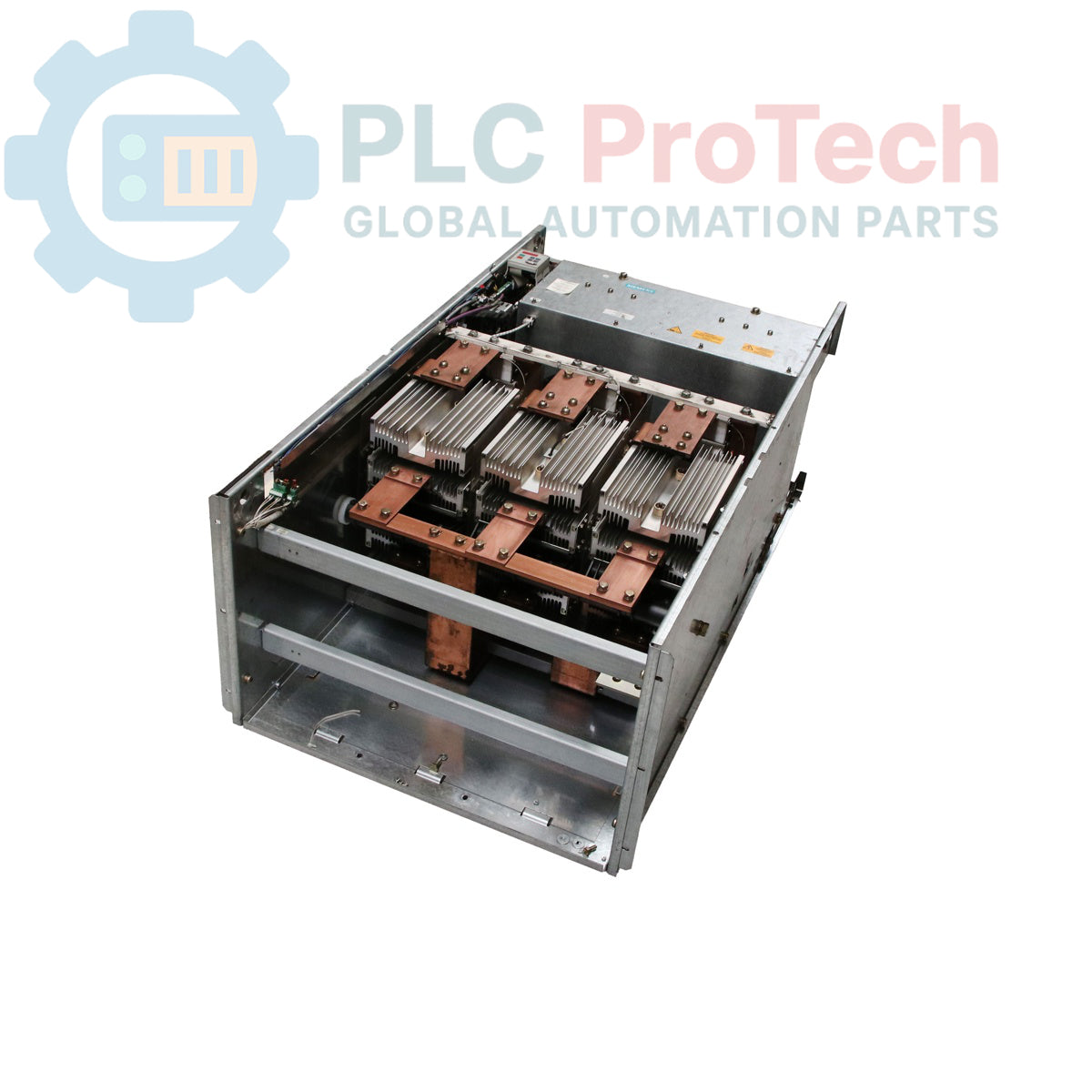
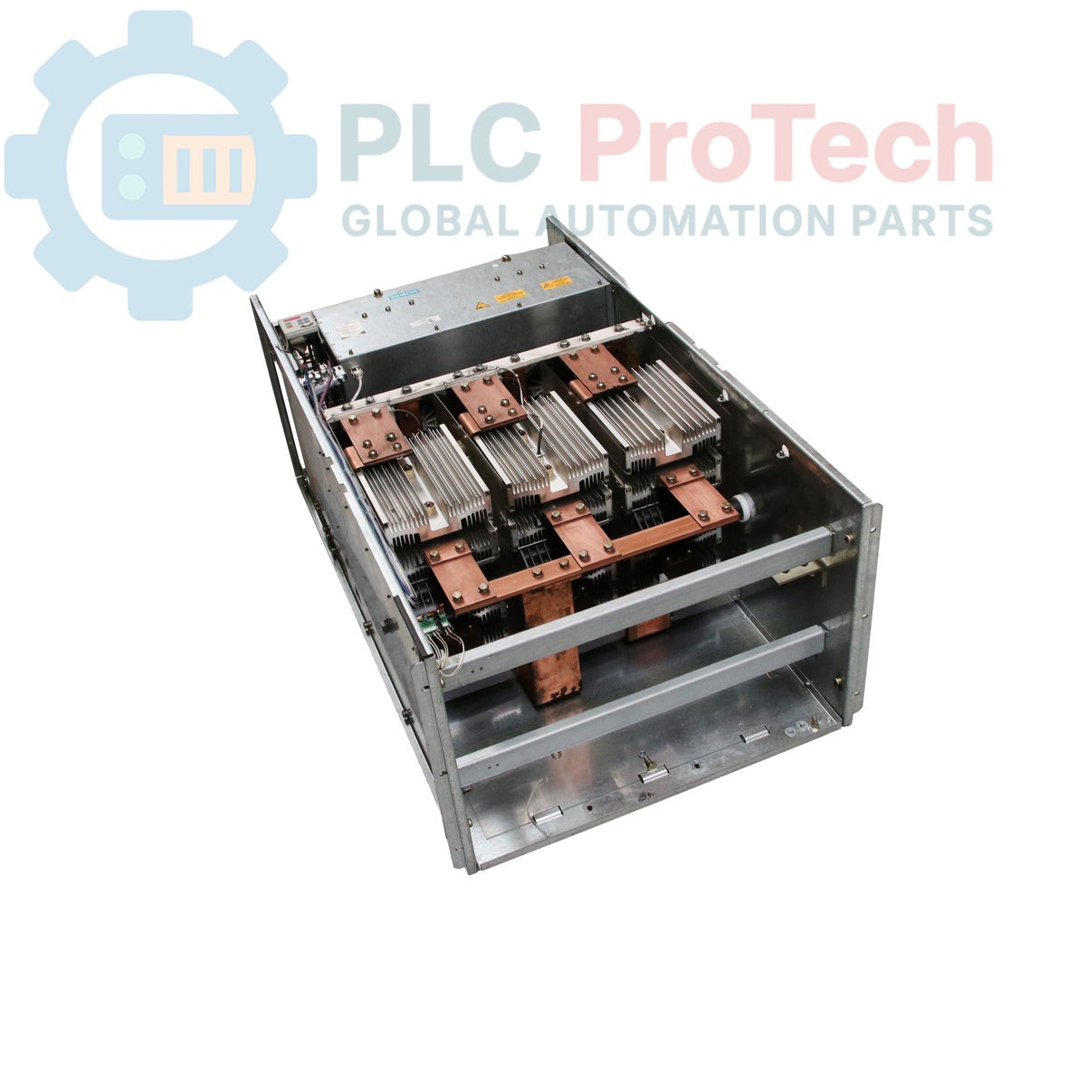
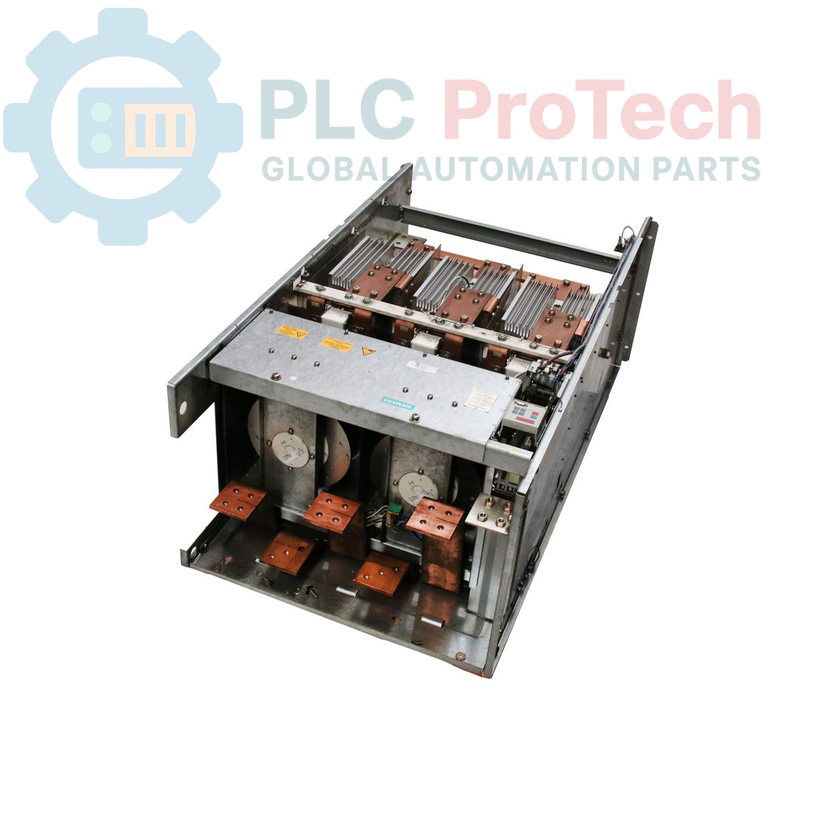
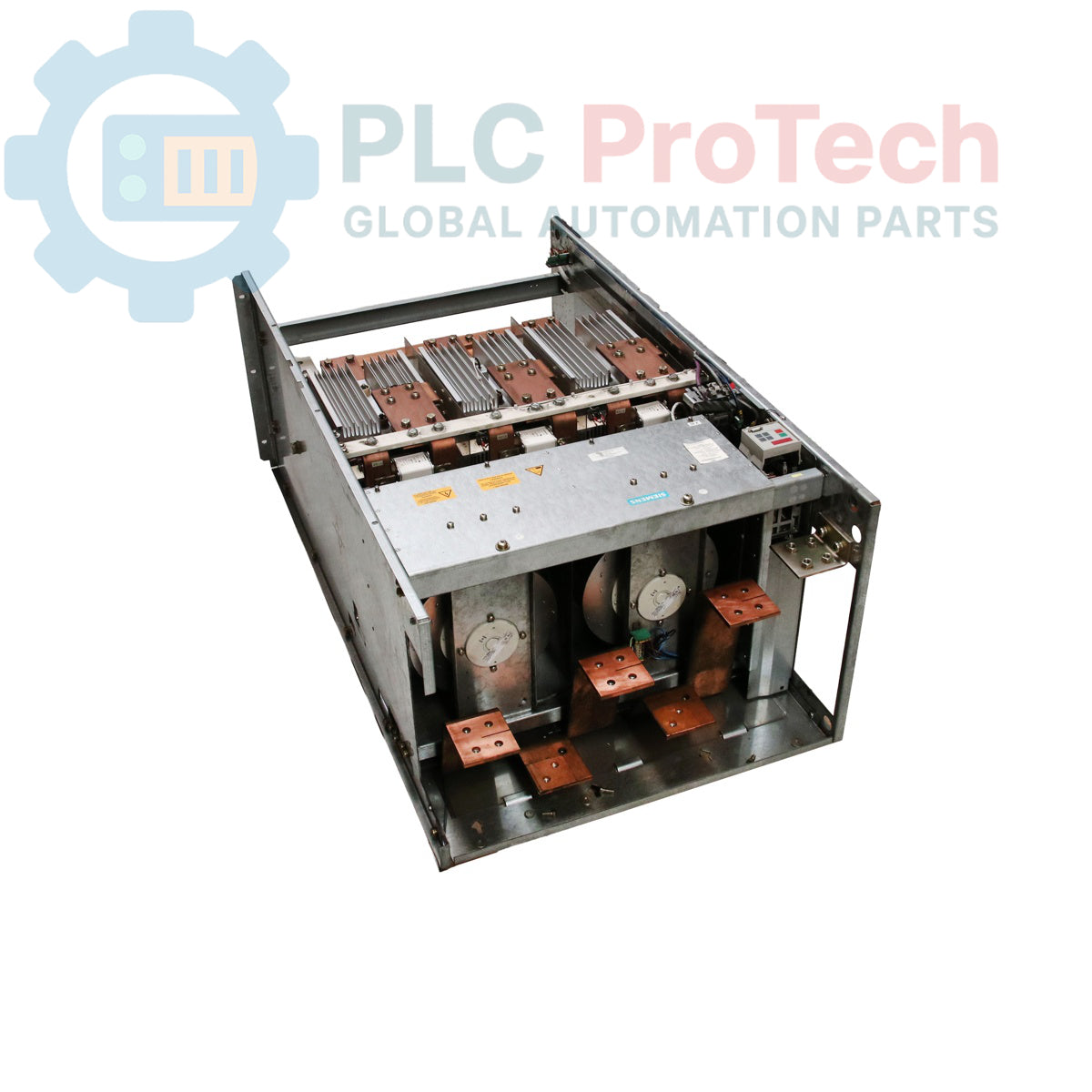
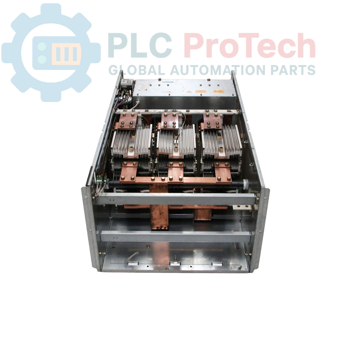
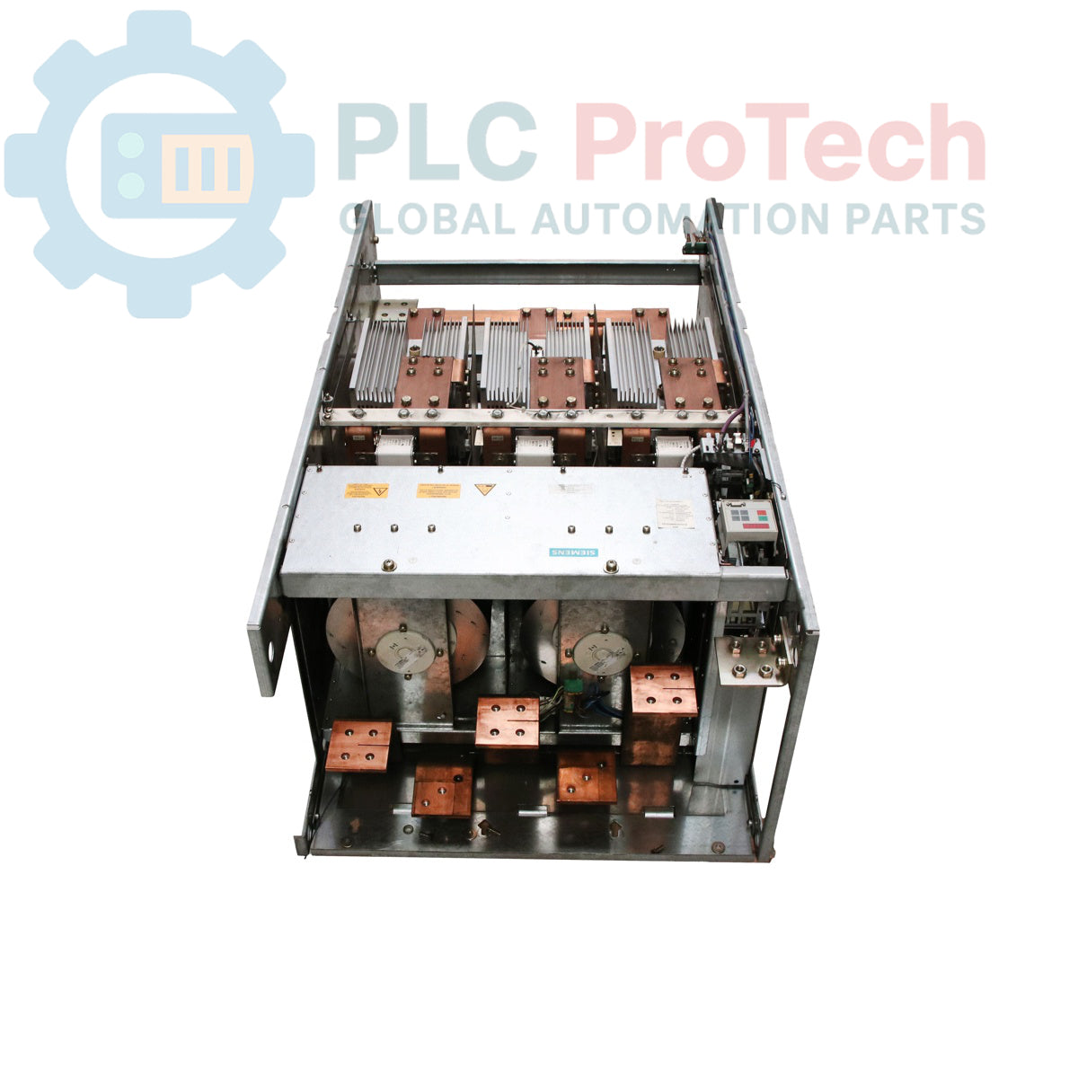
La topologie physique de cette unité d'onduleur à grande échelle utilise une construction de châssis ouvert IP00 non enfermée, destinée exclusivement à l'intégration à l'intérieur de baies d'armoires électriques spécialisées et climatisées. L'étage de puissance interne repose sur des modules transistors bipolaires à grille isolée (IGBT) à haute capacité configurés en pont de puissance à haute efficacité. En raison de son profil physique important et d'un poids net de produit de 345,20 kg, le module intègre des points de fixation mécaniques robustes dédiés ainsi que des voies de refroidissement interne par air forcé. Les signaux de commande et les impulsions de commande interfacent directement avec les cartes de régulation numériques du système maître via l'architecture de bus interne de l'entraînement, préservant une synchronisation à faible latence et protégeant la logique de traitement interne des interférences électromagnétiques haute tension locales.
Matrice des paramètres matériels vérifiés
| Paramètre |
Spécifications de performance |
| Modèle |
6SE7041-8EK85-0AA0 |
| Marque |
SIEMENS |
| Gamme d'entraînement |
SIMOVERT MASTERDRIVES |
| Classification de l'appareil |
Unité d'alimentation de remplacement / Unité de base d'entraînement |
| Phase du cycle de vie du produit |
Phase de retrait / Pièce de rechange héritée |
| Tension d'alimentation |
3 phases 380 VAC à 480 VAC, 50/60 Hz |
| Courant de sortie nominal |
1780 A |
| Indice de protection du boîtier |
IP00 (Format châssis pour installation en armoire) |
| Profondeur physique |
101,60 cm |
| Largeur physique |
63,50 cm |
| Hauteur physique |
157,50 cm |
| Poids net du produit |
345,20 kg |
| Code douanier |
85044086 |
| Réglementations sur le contrôle des exportations |
ECCN : N (Article non listé) |
Diagnostics d'ingénierie et FAQ d'application
Peut-on commander cette unité avec des options de communication spécialisées ou d'extension auxiliaire préinstallées ?
Le 6SE7041-8EK85-0AA0 représente un dispositif standard de remplacement d'unité d'alimentation de base. Il contient la matrice de puissance IGBT principale et les interfaces de commande, mais les cartes d'option supplémentaires — telles que les interfaces de communication Profibus (CBP2), les modules d'évaluation d'encodeur à impulsions (SBP) ou les cartes E/S étendues (EB1) — doivent être transférées de l'ancienne unité ou commandées séparément via le personnel commercial technique.
Quel est le risque fonctionnel de déployer une unité listée dans la phase de produit "Phase de retrait" ?
Le statut "Phase de retrait" indique que la série n'est plus la génération actuelle pour les nouvelles conceptions d'ingénierie. Cependant, elle reste entièrement prise en charge via des canaux techniques certifiés en tant que pièce de rechange critique d'usine afin de garantir que les installations en exploitation peuvent maintenir les systèmes hérités sans procéder à une mise à niveau complète et coûteuse du système d'entraînement.
Quelle infrastructure de refroidissement doit être vérifiée à l'intérieur de l'armoire hôte avant l'installation ?
Étant donné qu'il s'agit d'une unité châssis IP00 générant une chaleur importante à une charge de 1780 A, l'armoire électrique hôte doit fournir une ventilation forcée continue adéquate. Les voies d'entrée et de sortie d'air de l'armoire doivent correspondre aux exigences de débit volumétrique en pieds cubes par minute (CFM) du châssis pour éviter les points chauds internes et les déclenchements de surtempérature localisés.
Protocole de montage sur site et mise en service mécanique
-
Levage mécanique et dégagements de sécurité : Étant donné que le châssis pèse 345,20 kg et mesure 157,50 cm de hauteur, utilisez des ponts roulants certifiés ou des palans mécaniques reliés aux œillets de levage désignés par l'usine. Positionnez l'unité de base verticalement dans la baie, en maintenant les espaces de dégagement obligatoires autour des entrées et sorties d'air spécifiés par la disposition principale de l'équipement.
-
Tension mécanique des connexions des barres omnibus : Connectez les lignes AC entrantes à fort courant et les phases moteur sortantes à l'aide de barres omnibus en cuivre de haute qualité. Serrez toutes les vis mécaniques avec une clé dynamométrique calibrée selon la spécification de couple d'usine exacte pour les cadres à fort courant afin d'éliminer les micro-espaces, prévenir les arcs de contact à haute résistance et éviter les dommages thermiques aux bornes.
-
Mise à la terre galvanique et chemin de terre : Reliez une sangle de terre protectrice en cuivre de forte section et à faible impédance directement de la borne principale de mise à la terre du châssis au bus de terre principal de l'armoire. Éliminez toute peinture non conductrice ou film d'oxyde au point de contact pour établir une faible résistance et protéger les composants internes des bruits industriels en mode commun.
-
Câblage de commande et séparation des signaux : Faites passer toutes les lignes de commande basse tension, les liaisons à fibre optique et les câbles de capteurs externes par des canaux métalliques séparés et mis à la terre. Assurez un espacement minimum de 300 mm par rapport aux sections d'alimentation d'entrée et de sortie 480 V pour éviter que les harmoniques de commutation de l'onduleur ne perturbent les données de la boucle de commande.