Description
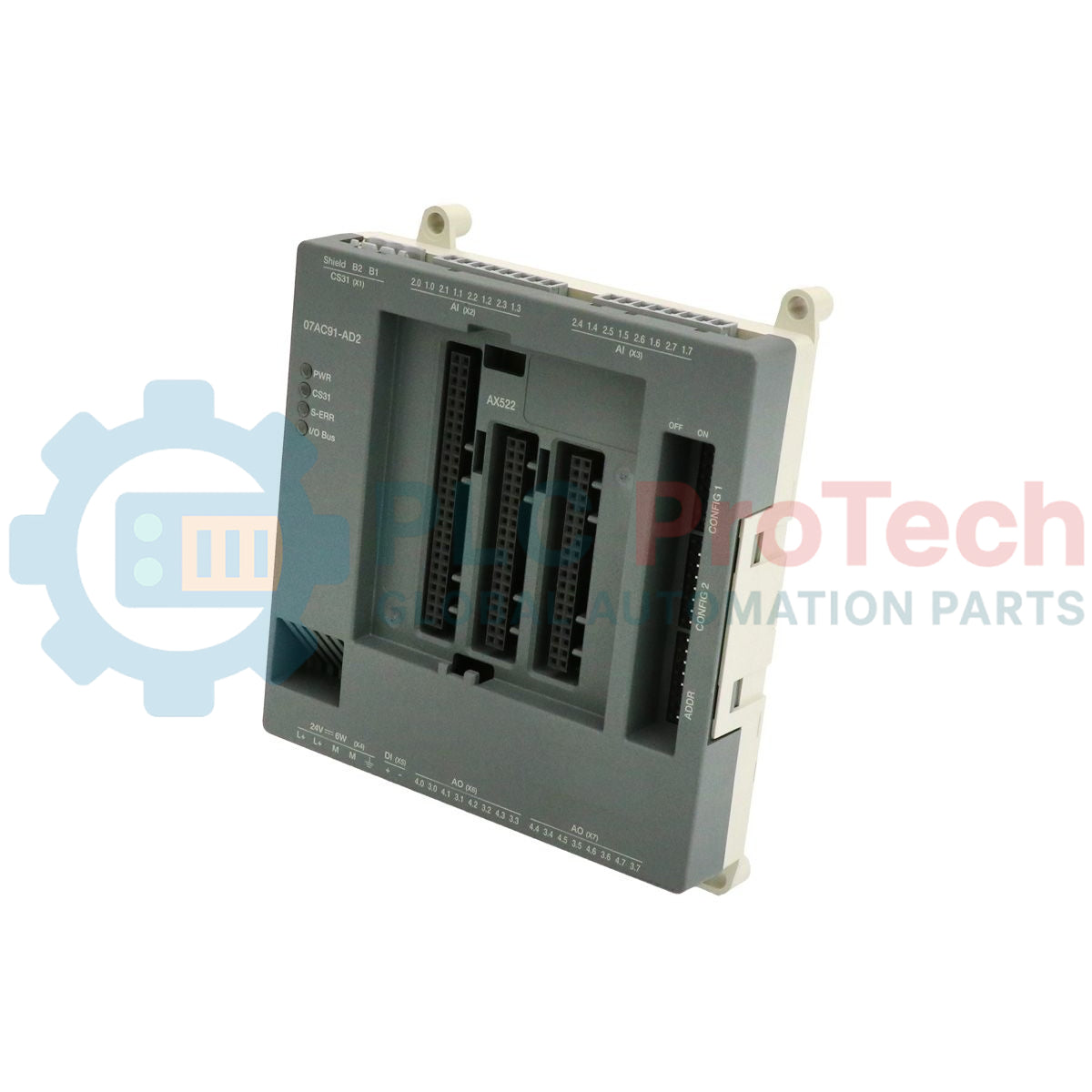
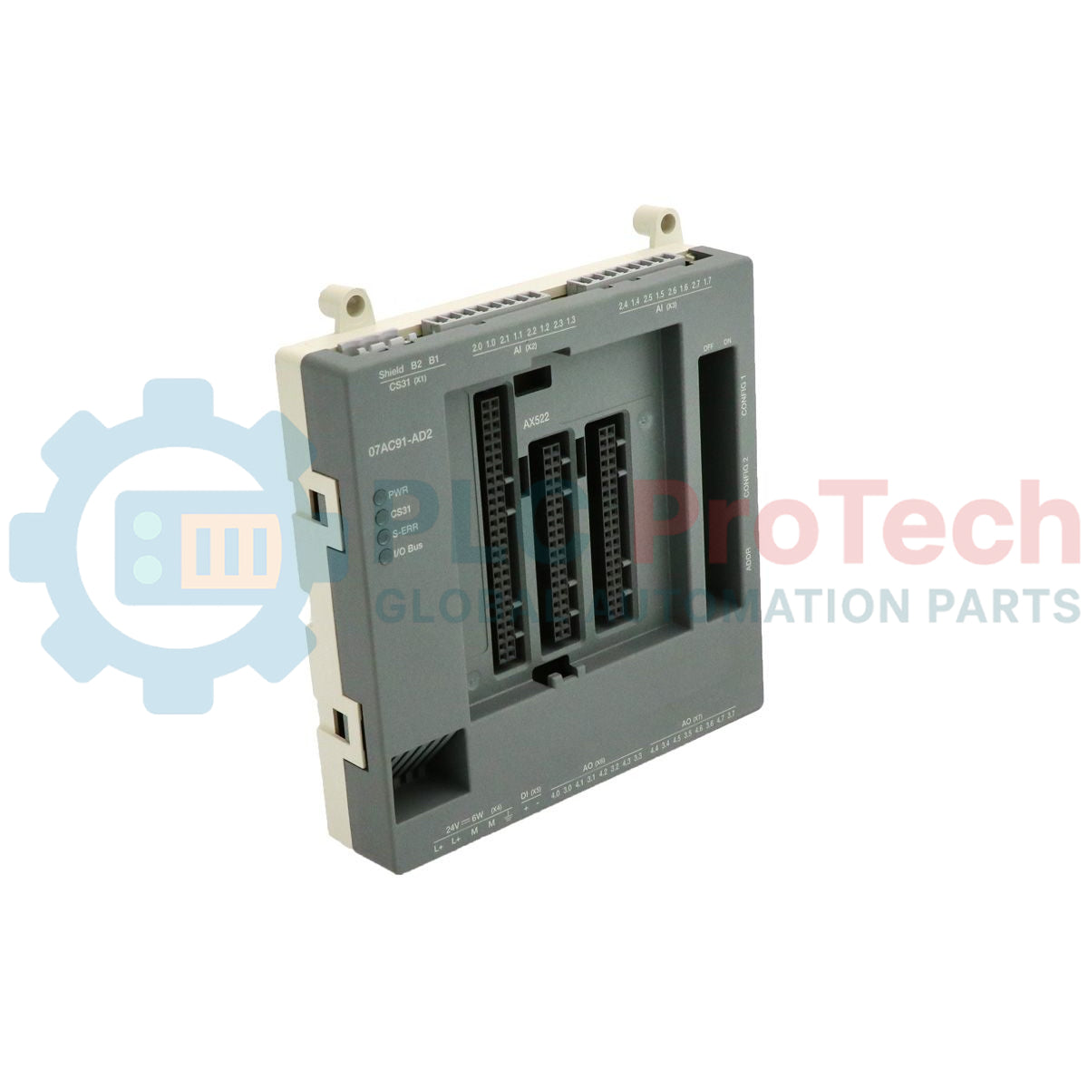
Designed for seamless integration into decentralized industrial automation networks, the ABB 1SAP800100R0010 serves as a highly reliable 07AC91-AD2 analog configuration input/output module. Operating on the robust CS31 fieldbus protocol, this unit facilitates high-density remote analog instrumentation handling without demanding excessive panel space. Featuring 8 analog inputs and 8 analog outputs with a resolution of 12 bits plus sign, it supports both voltage (U) and current (I) signals. Designed for adaptability, the hardware accommodates both 2-wire and 3-wire physical connection schemes, making it highly compatible with standard industrial sensors and transmitters.
Features
- Dual-functionality module providing 8 analog inputs and 8 analog outputs.
- Flexible parameterization for voltage and current signal ranges.
- 12-bit plus sign conversion resolution for stable measurement cycles.
- Integrated CS31 system bus interface for reliable distributed communication.
- Support for versatile 2-wire and 3-wire sensor and actuator configurations.
- Pluggable terminal blocks to simplify field wiring and quick-swap maintenance.
Applications
- Distributed SCADA telemetry and PLC I/O expansion networks.
- Pumping station control and industrial water treatment facilities.
- Machinery and process line control utilizing legacy CS31 fieldbus systems.
- HVAC and environmental chamber monitoring systems.
Technical Specifications
| Parameter |
Specification |
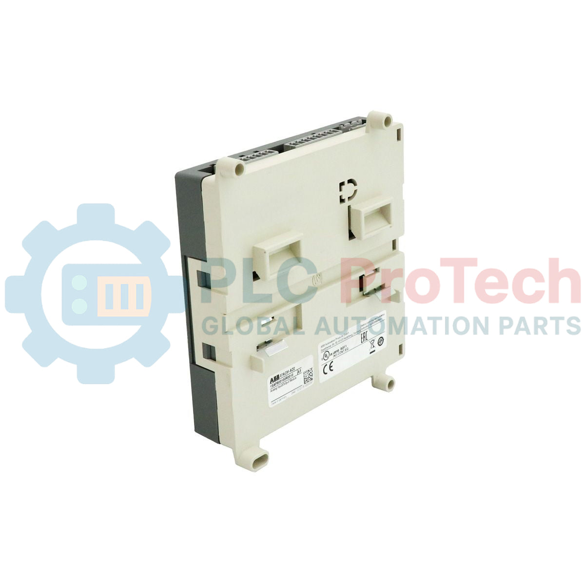
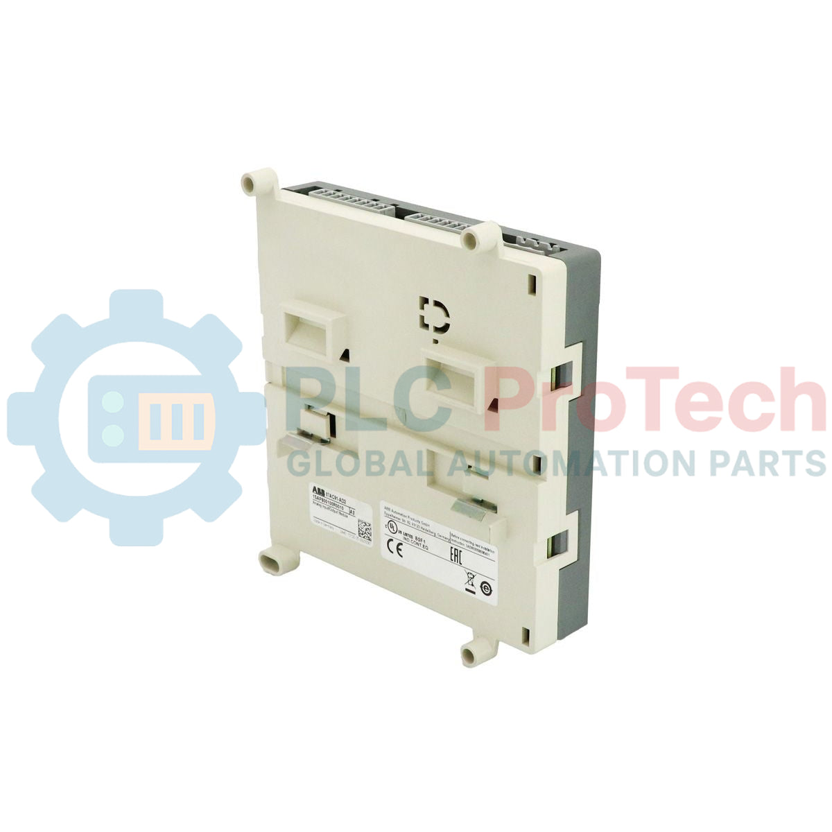
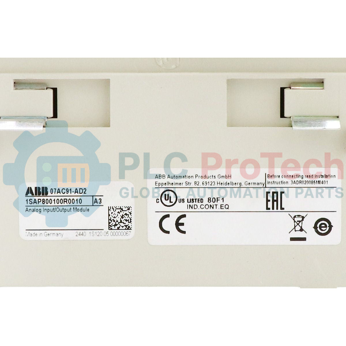
| Manufacturer |
ABB |
| Order Code |
1SAP800100R0010 |
| Model Designation |
07AC91-AD2 |
| Module Type |
Analog Configuration Input/Output Module |
| Analog Inputs |
8 (Configurable; Voltage/Current) |
| Analog Outputs |
8 (Configurable; Voltage/Current) |
| Resolution |
12 bits + sign |
| Auxiliary Power Supply |
24 VDC |
| System Bus |
CS31 Bus |
| Wiring Types Supported |
2-wire, 3-wire |
| Connection Method |
Pluggable terminals |
| Commodity Code |
85371091 |
| Shipping Weight (Calculated) |
0.20 kg |
| Package Dimensions (Calculated) |
120 mm x 80 mm x 60 mm |
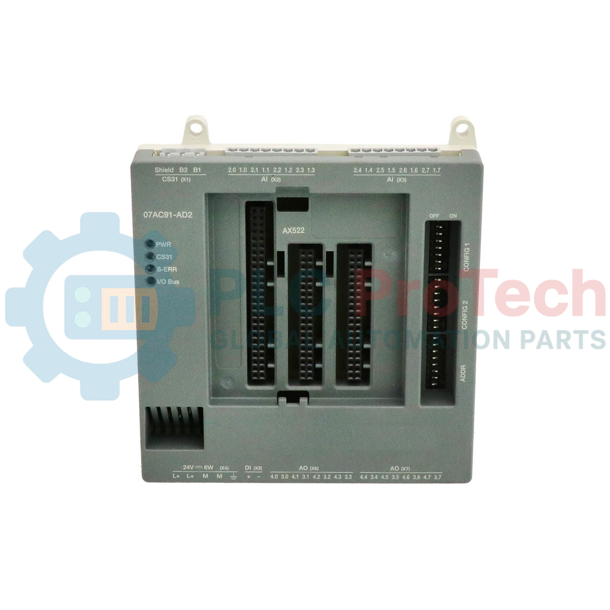
Connections and Interfaces
| Interface Group |
Terminal / Port Assignment |
Functional Details |
| Power Supply |
L+, M |
External 24 VDC auxiliary power input and system ground. |
| CS31 Fieldbus |
Bus1, Bus2, Shield |
System serial communication bus line and earth ground for shielding. |
| Analog Inputs |
I0+ to I7+, Common |
Channels configured for active/passive voltage or current loops. |
| Analog Outputs |
O0+ to O7+, Common |
Controlled voltage/current output signals for local actuators. |
Empirical Engineering Insights
Alternative Models & Compatibility
The 07AC91-AD2 module directly integrates with legacy AC31 master controllers and can be integrated into newer AC500 systems using an appropriate CS31 master bus module (such as the CI590 or integrated serial ports configured for CS31). Ensure that PLC configuration software contains the correct GSD or equivalent module configuration description profile matching the exact hardware index revision of the 1SAP800100R0010 to prevent system configuration mismatches during commissioning.
Application Pitfalls & Engineering Notes
Common communication errors on the CS31 bus typically stem from incorrect bus termination or long branch lines (stubs). Ensure a 120-Ohm termination resistor is present on the physical end-points of the CS31 network. Due to the high sensitivity of 12-bit analog conversions, never route analog input cables parallel to high-voltage lines or AC motor drives without maintaining standard separation and adequate physical shielding barriers.
Commissioning & Wiring Tips
Always configure the module's rotary address switches prior to system boot. The CS31 bus master scans address ranges on startup; dynamically changing addresses while the unit is active will cause a master CPU bus fault. Connect signal shield wires directly to the functional ground (FE) bus bar inside the control cabinet, and avoid grounding shields at both ends to eliminate the risk of destructive ground loop currents.
Installation Guidelines
CRITICAL WARNING
Isolate all electrical power sources before performing physical mounting, terminal connection, or address switch configuration. Failure to de-energize external 24 VDC sources and high-voltage supply lines can cause fatal electrical shock, module destruction, or erratic control loop operations.
1
Mount the module onto a standard 35mm DIN rail, ensuring the locking mechanism is engaged and the unit is firmly seated.
2
Configure the correct CS31 station address on the module using the hardware address switches on the enclosure.
3
Verify termination settings; apply a 120-Ohm resistor if this module occupies the physical end of the CS31 bus segment.
4
Wire the analog inputs and outputs using shielded, twisted-pair cables according to your 2-wire or 3-wire signal configuration.
5
Power up the 24 VDC auxiliary line and confirm that the module's status LEDs indicate a successful bus communication handshake.