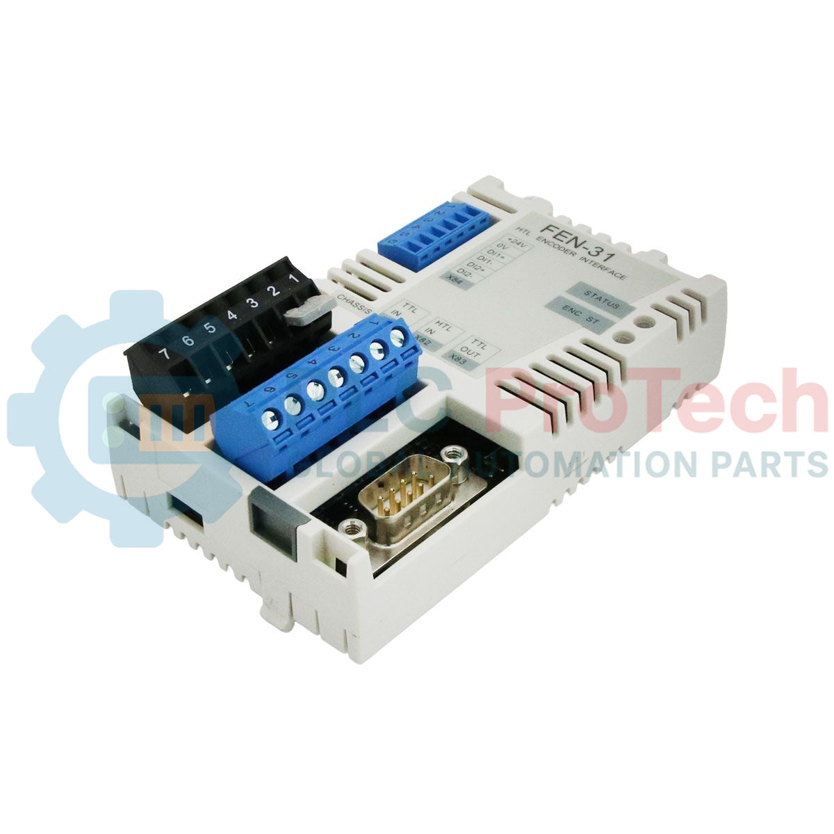
Description
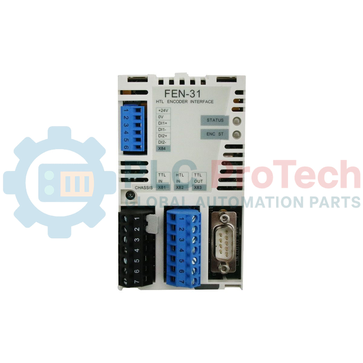
Integrating high-performance speed and position feedback into industrial drive networks, the ABB FEN-31 functions as a dedicated HTL encoder interface option module designed for direct installation into the option slots of ABB industrial drives. This module enables precise closed-loop control by processing differential or single-ended HTL signals, offering high noise immunity and dependable performance across long cable runs in electrically harsh environments. To ensure maximum system flexibility, the device features a built-in TTL emulation output link, permitting real-time speed/position data transmission to secondary controllers or master-follower configurations. With an integrated auxiliary power supply selectable between 15 VDC and 24 VDC, it eliminates the need for external encoder power sources, streamlining control cabinet footprints and wiring architectures.
Features
-
Robust HTL Interface: Supports standard single-ended and differential HTL (High-Threshold Logic) encoders for maximum signal stability.
-
Selectable Power Outputs: Direct onboard encoder power supply selectable via internal jumpers or drive parameters to deliver either 15 VDC or 24 VDC.
-
Integrated Signal Emulation: Features high-speed TTL emulation output channels to easily split encoder feedback to external PLCs or auxiliary tracking devices.
-
Fast Digital Inputs: Includes latching digital inputs for high-speed registration marks and synchronization index pulses.
-
Drive Slot Native Mounting: Slides directly into the drive inverter control unit option slots (e.g., Slot 2 on ACS880 series), drawing power and control bus communication internally.
Applications
-
Heavy-Duty Cranes & Hoists: Closed-loop control of hoisting motors requiring robust HTL signal transmission over long physical distances.
-
Continuous Metal Processing: High-torque speed regulation in steel rolling mills, slitting lines, and unwinding stations.
-
Paper & Pulp Machines: Synchronization of multiple sectional drive segments utilizing master-follower emulation lines.
-
Extruder & Mixer Control: Precise speed control under heavy load fluctuations in high-vibration processing environments.
Technical Specifications
| Parameter |
Specification Value |
| Manufacturer |
ABB |
| Model Designation |
FEN-31 (L502) |
| Module Type |
HTL Encoder Interface Module |
| Input Channels |
A+, A-, B+, B-, Z+, Z- (Differential or Single-ended HTL) |
| Encoder Power Supply Output |
15 VDC (max. 250 mA) or 24 VDC (max. 150 mA) selectable |
| Emulation Interface |
TTL Emulation Output |
| Max. Input Frequency |
200 kHz |
| Ingress Protection |
IP20 |
| Operating Temperature |
0 to 55 degC |
| Commodity Code |
85389091 |
| Export Control Class (ECCN) |
N |
| Shipping Weight |
0.56 kg |
| Package Dimensions |
18.0 x 26.0 x 9.0 cm |
Connections and Interfaces
| Terminal Block |
Pin Number |
Signal Assignment |
| X61 (Encoder Input) |
1 |
Channel A+ |
| 2 |
Channel A- |
| 3 |
Channel B+ |
| 4 |
Channel B- |
| 5 |
Channel Z+ (Index Reference) |
| 6 |
Channel Z- (Index Reference) |
| 7 |
VOUT (Encoder Power Supply Output) |
| 8 |
COM (Supply Ground Reference) |
| X62 (Emulation/DI) |
1 |
DI1 (Latch / Fast Digital Input 1) |
| 2 |
DI2 (Latch / Fast Digital Input 2) |
| 3-6 |
TTL Emulation Output Channels (A/B/Z differential) |
| 7-8 |
Shield / Functional Earth Reference |
Empirical Engineering Insights
Alternative Models & Compatibility
The FEN-31 is designed to support HTL signals specifically. If your application switches to resolver-based feedback, you must migrate to the FEN-21 resolver interface. For high-resolution absolute encoders using EnDat, SSI, or BiSS-C protocols, select the FEN-11 module. Note that firmware parameter mappings in Parameter Group 91 (Encoder configuration) must be manually updated in the ACS880 or ACS850 drive interface when swapping feedback boards, as the drive does not automatically auto-detect encoder resolution or signal phase alignments.
Application Pitfalls & Engineering Notes
A common failure point on-site relates to exceeding the maximum output current rating of the onboard encoder supply. When selecting 24 VDC output, the absolute limit is 150 mA. If an HTL encoder with high internal power draw or heavy line loading is utilized, the voltage level will drop, resulting in intermittent position loss faults (such as drive fault 7301 Encoder or 7381 Encoder feedback). For runs exceeding 100 meters, it is recommended to power the HTL encoder via an external 24 VDC cabinet supply and route only the signal lines through the FEN-31, ensuring common grounds are securely bridged.
Commissioning & Wiring Tips
To prevent electrical noise interference from the motor cables from corrupting HTL pulses, always use twisted-pair shielded cable (individually shielded pairs for A+/A-, B+/B-, Z+/Z-). Shielding must be terminated at the 360-degree grounding clamp on the drive's control unit frame. Under no circumstances should the cable shield be terminated at both the drive and the motor-end encoder frame unless a robust, high-frequency equipotential bonding strip is present between the motor and control cabinet.
Installation Guidelines
CRITICAL WARNING: Hazardous voltage levels are present within the drive enclosure. Ensure the drive main AC disconnect is locked out and tagged out. Wait at least 5 minutes to allow the internal DC bus capacitors to discharge to safe levels (below 50 VDC) before removing the drive cover or inserting the FEN-31 module. Verification of zero voltage on the DC bus terminals is mandatory.
1
Ensure the drive is completely de-energized, the internal DC capacitors are fully discharged, and safe grounding procedures are executed.
2
Align the FEN-31 plastic housing guide rails with Option Slot 2 (or Slot 1 as designated in your control schematic) of the drive's control board.
3
Gently press the module forward until the multi-pin connector on the rear of the card mates flush with the drive slot receptacle.
4
Tighten the grounding/mounting screw to a torque rating of 0.8 Nm to secure mechanical stability and reliable electrical grounding.
5
Wire the HTL encoder terminal connections to block X61, clamp shields to the grounding frame, reassemble the drive cover, and apply system power for parameter configuration.