Deskripsi
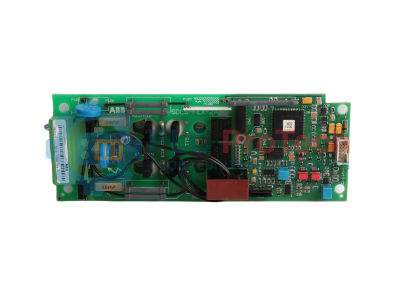
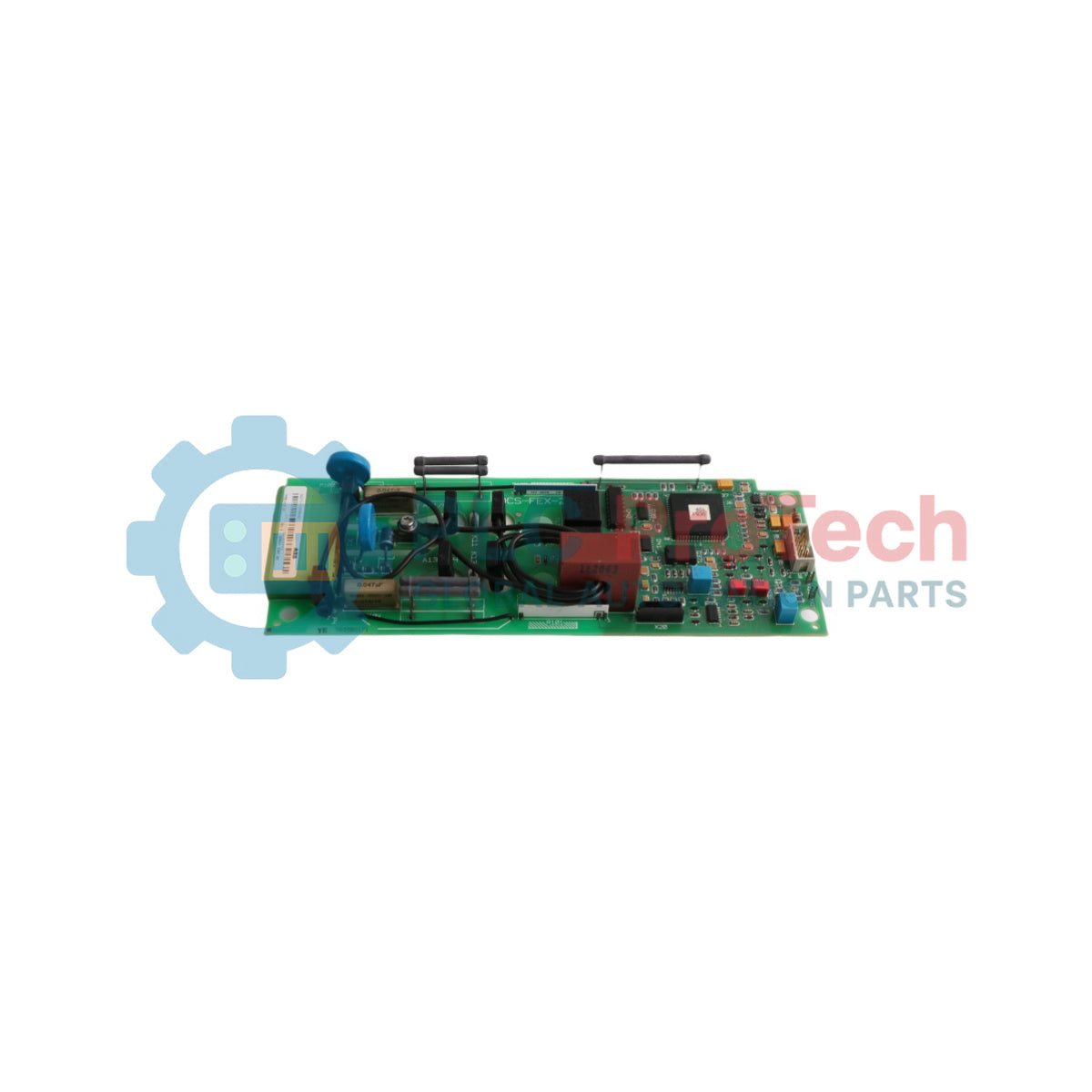
ABB SDCS-FEX-2A adalah papan sirkuit eksitasi medan dan catu daya satu fasa terintegrasi yang dirancang untuk pemasangan internal dalam modul konverter armatur. Berfungsi sebagai papan eksitasi medan digital, modul ini terdiri dari bagian daya terintegrasi dan bagian prosesor kontrol onboard yang menghubungkan semua komponen internal secara elektrik dan mekanik.
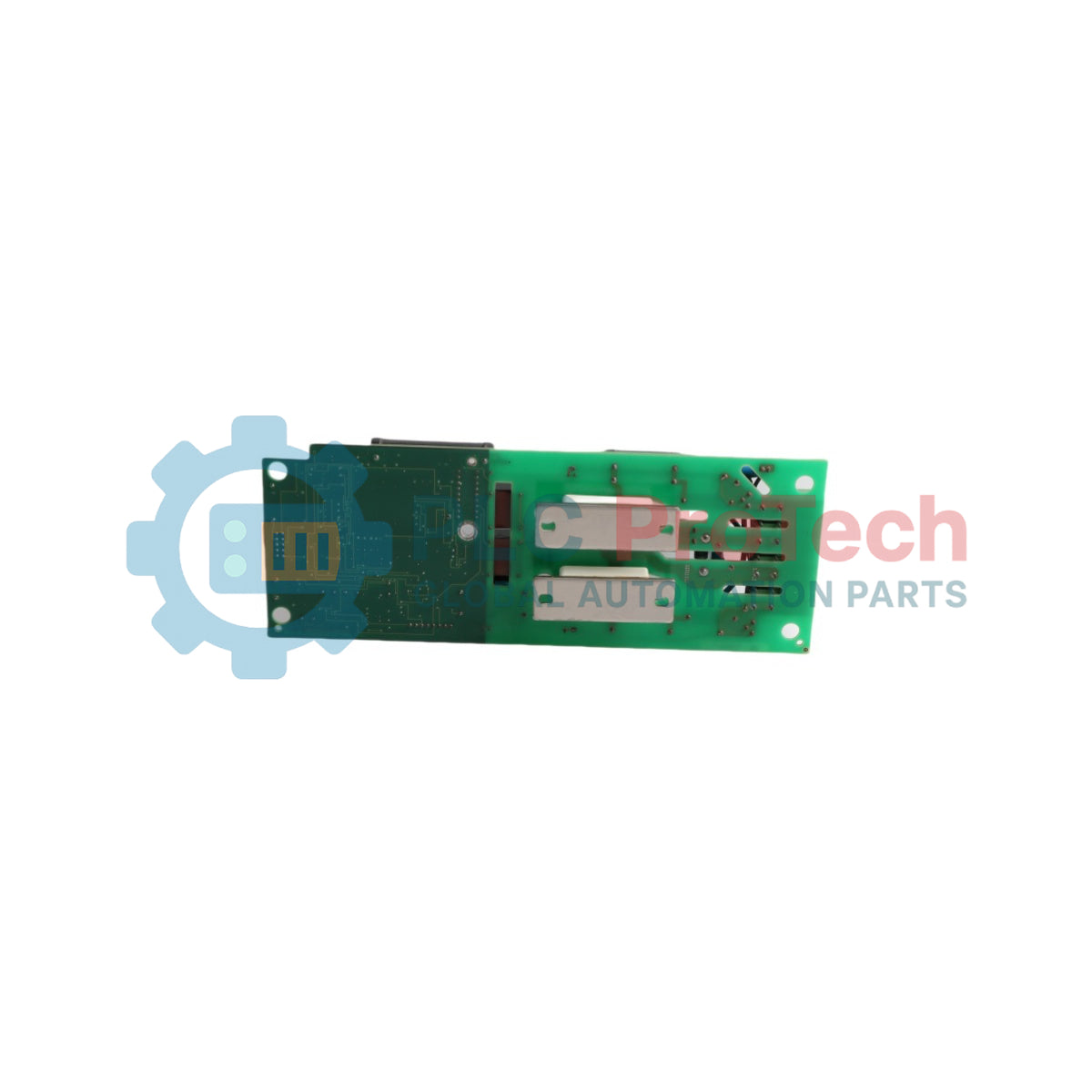
SDCS-FEX-2A dirancang khusus untuk pemasangan di dalam modul konverter ABB DCS tipe C1, C2, dan C3 bersama papan catu daya elektronik SDCS-POW-1, tetapi sepenuhnya tidak kompatibel dengan ukuran rangka C4. Beroperasi dengan rentang tegangan masukan satu fasa yang luas dari 110V hingga 500V AC dan kapasitas arus maksimum 16A, 3ADT311500R1 menggunakan tata letak mikrokontroler digital penuh untuk menskalakan resistor beban aktifnya secara dinamis, memastikan resolusi sinyal optimal di antara rentang pemilihan otomatis antara 3A dan 16A.
Fitur
-
Penyearahan Jembatan Setengah Terkontrol: Dibangun menggunakan dua modul dioda-tiristor internal yang dikonfigurasi sebagai jembatan setengah terkendali satu fasa untuk kontrol lilitan medan motor yang efisien.
-
Mikrokontroler 80C198 Onboard: Menampilkan unit eksekusi mikrokontroler 80C198 tertanam khusus yang menjalankan algoritma loop firmware PI lokal untuk stabilisasi arus langsung.
-
Skala Beban Otomatis: Memilih resistor beban perangkat keras internal secara dinamis tergantung pada parameter medan nominal motor untuk memaksimalkan akurasi kontrol.
-
Pertahanan Lonjakan Terintegrasi: Dilengkapi dengan dua Metal Oxide Varistor (MOV) yang menyediakan peredaman lonjakan tegangan transient secara simultan di sisi masukan AC dan sirkuit output DC induktif.
Aplikasi
- Eksitasi medan motor internal dan regulasi arus DC loop tertutup di dalam unit konverter ABB DCS500 dan DCS600.
- Rangkaian penggerak industri berat termasuk kelompok kipas kecepatan variabel, infrastruktur derek hoist, dan sistem ekstrusi berat.
Spesifikasi Teknis
| Parameter |
Spesifikasi |
| Produsen |
ABB |
| Penunjukan Model |
SDCS-FEX-2A |
| ID Produk / Nomor Pesanan |
3ADT311500R1 |
| Arsitektur Kontrol |
Mikrokontroler Digital 80C198 |
| Rentang Tegangan Masukan AC |
110V hingga 500V AC satu fasa |
| Output Arus Maksimum |
16A |
| Rentang Pemilihan Arus Otomatis |
Dari 3A hingga langkah resolusi 16A |
| Protokol Antarmuka Serial |
Tautan RS485 ke papan SDCS-CON-x |
| Alamat Perangkat Komunikasi Tetap |
Nomor node = 1 |
| Status Jenis Bagian |
Asli / Baru |
| Negara Asal |
Finlandia (FI) / Jerman (DE) |
| Berat Pengiriman (Dihitung) |
0,65 kg |
| Dimensi Paket (Dihitung) |
270 mm x 195 mm x 80 mm |
Wawasan Teknik Empiris
Model Alternatif & Kompatibilitas
Modul SDCS-FEX-2A dirancang khusus untuk integrasi bingkai ke dalam modul konverter tipe DCS C1, C2, dan C3. Jangan mencoba pemasangan struktural mekanis atau listrik di dalam ruang konverter tipe C4 yang lebih besar, karena aliran ventilasi, ukuran struktural, dan kabel jalur komunikasi sama sekali tidak dapat dipertukarkan. Modul ini mempertahankan pengenal routing jaringan RS485 tetap permanen pada Alamat Node 1, yang memerlukan kepatuhan konfigurasi ketat pada tata letak papan master SDCS-CON-x yang menyertainya.
Jebakan Aplikasi & Catatan Teknik
Selama inisialisasi, mikrokontroler onboard bergantung pada streaming parameter waktu nyata dari memori prosesor armatur utama melalui kabel datar X14. Jika terjadi gangguan pada tautan komunikasi RS485 atau nilai konfigurasi tabel parameter gagal diterapkan dengan benar, perangkat lunak kontrol medan akan gagal mengatur resistor beban internal, menyebabkan kesalahan pelacakan arus nol. Selain itu, saat menguji nilai loop keluaran melalui baris terminal X20:, multimeter eksternal harus mempertahankan resistansi operasional internal lebih dari 1M Ohm untuk mencegah kondisi hubung singkat atau kesalahan pengukuran.
Pedoman Instalasi
PERINGATAN KRITIS: POTENSIAL TEGANGAN TINGGI AC/DC YANG MEMATIKAN
Isolasi, matikan, dan kunci pengaman semua jalur feeder AC tiga fase yang masuk serta tautan tegangan eksitasi satu fase yang berbeda yang memasok rangka konverter. Kapasitor penyimpanan internal menyimpan muatan listrik energi tinggi setelah jalur pasokan diputus. Beri waktu minimal 15 menit untuk pelepasan aman agar muatan benar-benar habis, dan verifikasi keadaan tanpa energi di semua terminal dengan alat penguji terkalibrasi sebelum menangani rangkaian internal.
1
Pasang tali pengaman grounding statis yang sudah diverifikasi ke lengan Anda dan kencangkan kabel grounding dengan erat pada elemen bingkai baja yang tidak dicat dari kotak kontrol yang terhubung ke tanah.
2
Lepaskan dengan hati-hati rakitan koneksi pita datar tegangan rendah dari port antarmuka X14: dan buka sekrup dengan aman jalur pasokan AC utama serta jalur keluaran medan induktif motor.
3
Selaraskan bingkai kartu pengganti ke saluran pemasangan dalam di samping komponen daya SDCS-POW-1, kencangkan perangkat keras pengunci dengan torsi untuk mengunci jalur loop tanah, dan sambungkan kembali semua kabel.