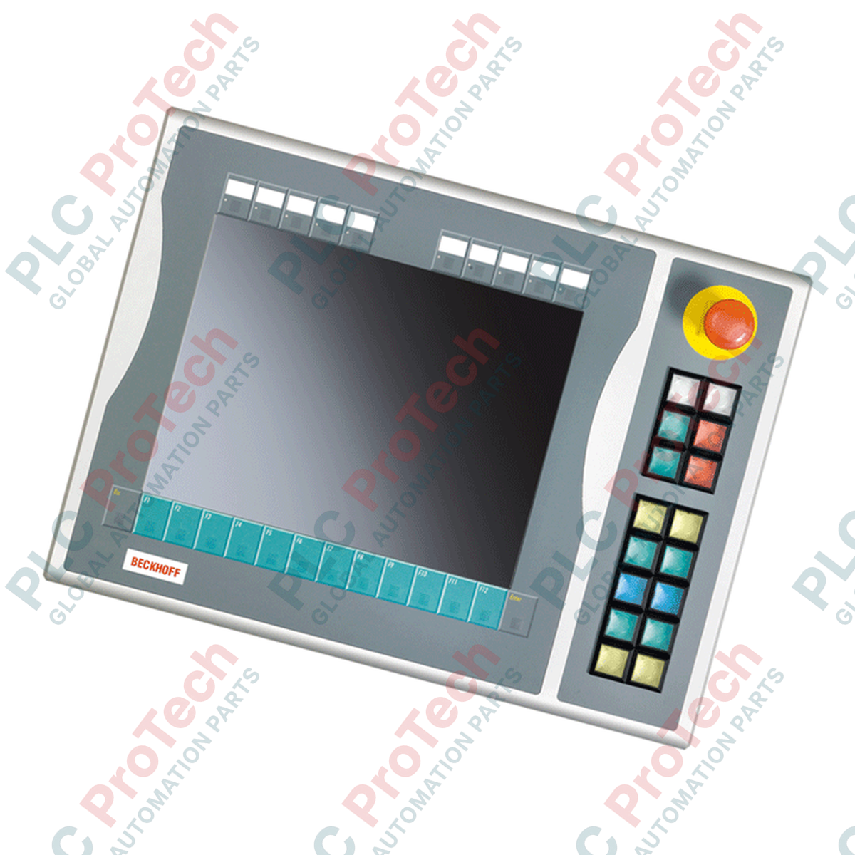
Description
Designed for physical operator control integration, the Beckhoff C9900-E557 provides a ruggedized, right-side push-button extension for CP6xxx and CP7xxx Control Panels and Panel PCs equipped with 15-inch displays and function keys. This expansion module bridges the gap between digital HMI commands and direct physical actuation, enabling critical control signals to bypass network latency during setup or emergency conditions. Operating in its service phase, this module ensures legacy compatibility and direct physical feedback on industrial production floors.
Features
-
Physical Control Interface: Equipped with 16 square push-button keys (30 x 30 mm, Siemens Signum type) featuring integrated signal lamps.
-
Dedicated Safety Control: Integrated Siemens Signum emergency stop key, directly wireable for hardwired safety-loop integration.
-
Customizable Layouts: Insertable labels for push-button caps allow custom engraving or labeling to match specific operator function designs.
-
Hybrid Communication: All 16 push-buttons utilize a dual-contact architecture, transmitting one normally-open (NO) contact via CP-Link or USB, while a second NO contact is wireable directly to local terminal rows.
-
Independent Indicator Control: Signal lamps are driven directly via the host panel interface (CP-Link or USB), allowing flexible software-driven feedback.
Applications
- Custom operator stations for automotive manufacturing and assembly plants.
- Heavy industrial machinery requiring redundant physical control switches alongside touch interfaces.
- Retrofits of legacy CP6x12-00xx and CP7x12-00xx installations requiring standard compliance upgrades.
Technical Specifications
| Parameter |
Specification |
| Manufacturer |
Beckhoff Automation |
| Model Number |
C9900-E557 |
| Compatible Host Panels |
CP6x12-00xx and CP7x12-00xx (15-inch displays) |
| Mounting Configuration |
Right-side panel attachment |
| Operator Elements |
16x push-buttons with signal lamps (Siemens Signum, 30 x 30 mm) |
| Emergency Stop |
1x Siemens Signum emergency stop key, directly wireable |
| Communication Interface |
USB or CP-Link (primary NO contacts and lamp signals) |
| Direct Output Terminals |
Internal terminal row for hardwired secondary NO contacts |
| Country of Origin |
Germany |
| Shipping Weight (Calculated) |
5.0 kg |
Connections and Interfaces
| Connector / Terminal Row |
Function / Assignment |
| CP-Link / USB Bus Connection |
Transmits digital keypresses (1st NO contact) and controls LED signal lamps. |
| Internal Terminal Strip |
Direct screw terminal interface for secondary hardwired NO contacts. |
| E-Stop Contact Blocks |
Independent, direct-wire contacts for safety relay or safety PLC connection. |
Empirical Engineering Insights
Alternative Models & Compatibility: Ensure your host model is a true 15-inch display (CP6x12 or CP7x12). Variations of this extension exist for left-side mounting and alternative display sizes; swapping left and right side models is not mechanically possible due to the asymmetric housing alignment and integrated wiring paths.
Application Pitfalls & Engineering Notes: Because the primary NO signals and indicator lights run over CP-Link or USB, do not use the software-interfaced button contacts for safety-critical interlocking or safety functions. Use the hardwired terminal row for safety-related actions, and route the Emergency Stop directly to certified safety monitoring relays.
Commissioning & Wiring Tips: To maintain the host panel's overall IP rating, ensure the interface gasket between the C9900-E557 housing and the Control Panel is properly seated and tightened to OEM specifications during installation. If using long USB segments, ensure an active repeater or high-quality shielded USB cables are utilized to prevent transmission drops of the button status.
Installation Guidelines
CRITICAL WARNING
Isolate all electrical power sources before commencing installation. De-energize both the primary Control Panel feed and any external auxiliary supply voltages wired to the internal terminal strip. Secure against accidental reconnection.
1
Carefully remove the right-side cover plate from the compatible Beckhoff CP6xxx or CP7xxx Control Panel.
2
Align the C9900-E557 extension module with the mounting tracks, ensuring the rubber seal is completely flush and free of folds.
3
Route internal connection cables (USB/CP-Link internal connector) to the designated interface board on the host panel.
4
Wire the secondary direct-acting terminals and safety-critical emergency stop lines using appropriate wire gauges and terminal tools.
5
Secure all mechanical fasteners, close the housing enclosure, apply power, and verify button functionality and E-stop circuit continuity.