Description
Integrating directly into the modular PC/104 bus architecture, the Beckhoff CX1100-0930 provides highly reliable, capacitive-based uninterruptible power supply capabilities for CX series Embedded PCs. This module is engineered to bridge short-term voltage fluctuations and secure volatile operational data by initiating a controlled shutdown sequence during primary power failures. By employing capacitive storage technology, it offers a maintenance-free alternative to traditional battery-backed systems, operating efficiently without risk of degradation or chemical leakage in harsh thermal environments.
Features
-
Capacitive Storage Medium: Features a 40 As capacity that eliminates regular battery maintenance intervals and shelf-life concerns.
-
Adjustable Retention Time: Provides load-dependent holdup durations that can be fully customized to meet specific system requirements.
-
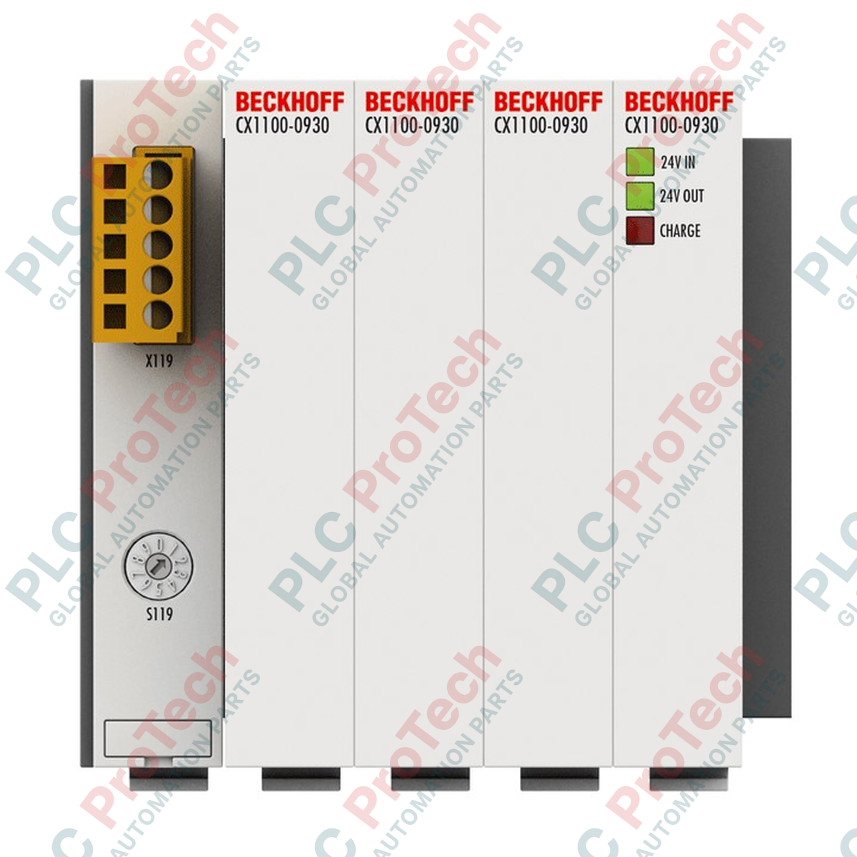
Local Diagnostics indicators: Three integrated LEDs provide real-time status feedback for 24 V DC input, 24 V DC output, and capacitive charge state.
-
Embedded Bus Interface: Communicates directly via a high-speed, 16-bit ISA bus conforming to the standard PC/104 hardware layout.
-
Industrial Protection: IP20-rated housing built to resist severe industrial vibration and shock according to European standards.
Applications
- Securing persistent memory (NOVRAM writing operations) during sudden primary power interruptions.
- Enabling orderly, controlled OS shutdowns for Windows CE or Windows Embedded systems.
- Protecting localized processing nodes in networks prone to voltage sags and grid fluctuations.
Technical Specifications
| Parameter |
Specification |
| Manufacturer |
Beckhoff |
| Model / Article Number |
CX1100-0930 |
| Input Voltage |
24 V DC (-15% / +20%) |
| Storage Technology |
Capacitive |
| Capacity |
40 As (Ampere-seconds) |
| Max. Output Current |
2.0 A (at 24 V DC) |
| Charging Current |
Max. 4.0 A |
| Retention Time |
Adjustable, load-dependent |
| CPU Bus Interface |
16-bit ISA (PC/104 standard) |
| Max. Power Loss |
2.0 W |
| Diagnostic Displays |
LEDs for 24 V DC Input, 24 V DC Output, and Charge |
| Protection Rating |
IP20 |
| Operating Temperature |
0 to 55 degC |
| Storage Temperature |
-25 to 85 degC |
| Relative Humidity |
95%, non-condensing |
| Vibration / Shock Resistance |
Conforms to EN 60068-2-6 / EN 60068-2-27 |
| EMC Immunity / Emission |
Conforms to EN 61000-6-2 / EN 61000-6-4 |
| Dimensions (W x H x D) |
95 mm x 100 mm x 91 mm |
| Net Weight |
650 g |
| Shipping Weight (Calculated) |
2.0 kg |
Empirical Engineering Insights
Alternative Models & Compatibility
The CX1100-0930 is mechanically and electrically dedicated to the legacy CX1000 and CX1020 Embedded PC systems. If replacing an older module or a battery-backed variant (such as the CX1100-0900 series), confirm that your operating system image contains the necessary registry settings to interact with the 16-bit ISA bus address allocation. This module will not directly interface with newer CX2000 systems using PCI Express-based system interfaces.
Application Pitfalls & Engineering Notes
Because this module utilizes capacitive storage, the 40 As total energy capacity is highly dependent on the total active current draw of the CPU stack. High processing loads or extensive connected I/O terminals during a power-fail transition will drastically shorten the retention window. System integrators must design efficient, non-blocking data-dump routines in TwinCAT to write persistent data (NOVRAM) to the boot media immediately upon detecting a mains failure signal.
Commissioning & Wiring Tips
During initial commissioning, verify that the 24 V DC power supply is sized to handle the maximum charging current overhead of 4.0 A. If the primary supply exhibits a voltage sag below 20.4 V DC (the lower limit of the -15% tolerance) during the module's charging phase, the system may initiate an unintentional low-voltage shutdown sequence. Check that the "Charge" LED switches from flashing (charging active) to solid green (fully charged) within the boot-up timeline.
Installation Guidelines
CRITICAL WARNING
Isolate and lock out all 24 V DC system power before executing assembly or disassembly. Capacitive units retain an electrical charge even after primary power disconnection. Allow a minimum of three minutes for internal energy dissipation before handling the physical bus connectors or dismantling the PC/104 block.
1
Align the CX1100-0930 interface with the adjoining CX series module, ensuring the 16-bit ISA (PC/104) male and female pin connectors match precisely without offset.
2
Slide the module onto the standard DIN rail until the locking latch clicks firmly, and secure the module stack together using the mechanical side-locking mechanism.
3
Connect the 24 V DC primary supply cables to the terminals, verifying polarity, and ensure a low-impedance connection to the central functional earth terminal.
4
Energize the power source and verify that the "Input" and "Charge" LEDs illuminate, indicating active voltage input and ongoing capacitive energy buffering.