Description
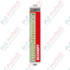
To enable reliable communication across long-distance industrial networks, the Beckhoff EK1501-0100 integrates multi-mode fiber optic media conversion directly with EtherCAT Terminal systems. This device bridges the gap between 100BASE-FX optical networks and standard RJ45 copper connections, serving as a highly secure communication node. By utilizing multi-mode glass fiber, this coupler allows connection distances of up to 2000 meters between individual stations, bypassing the electromagnetic interference vulnerabilities of traditional copper cabling.
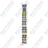
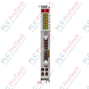
The module features an integrated three-digit decimal ID switch, which allows the configuration of up to 4096 unique station IDs. This hardware-defined addressing is critical for Hot Connect topologies, enabling system modules to be connected or disconnected during live operation. The coupler generates an internal E-bus current of up to 2000 mA, powering the connected ELxxxx terminal series directly from the incoming 24 V DC system supply.
Key Technical Features
-
High-Distance Fiber Connection: Supports 100BASE-FX multi-mode fiber (50/125 um glass fiber) using a robust SC Duplex connection.
-
Hardware Address ID Switch: Configures station IDs up to 4096 via physical rotary switches, facilitating complex Hot Connect applications.
-
Robust Power Supply: Accepts 24 V DC system power and supplies up to 2000 mA current to the internal E-bus.
-
Electrical Isolation: Complete 500 V galvanic isolation between the power contacts, internal supply voltage, and Ethernet ports.
-
Ex Certification: Standardized with ATEX Zone 2 rating (II 3 G Ex nA IIC T4 Gc) for hazardous explosive atmospheres.
Industrial Applications
-
Wind Power & Renewable Energy: Optical media conversion prevents lightning damage and noise propagation between tower base and nacelle.
-
Water/Wastewater Treatment: Bridges expansive process areas spanning up to 2000 meters without active repeaters.
-
Automotive Assembly Lines: Leverages Hot Connect IDs for tool changers, allowing quick physical re-tooling without software reconfiguration.
-
Hazardous Zones: Safely deploys I/O nodes in explosive-prone environments requiring ATEX Zone 2 ratings.
Technical Specifications
| Parameter |
Specification |
| Manufacturer |
Beckhoff Automation GmbH & Co. KG |
| Model Number |
EK1501-0100 |
| Protocol |
EtherCAT |
| Data Transfer Medium |
Multi-mode glass fiber 50/125 um |
| Max. Distance Between Stations |
2000 m (100BASE-FX) |
| Bus Interface |
1 x SC Duplex |
| Power Supply |
24 V DC (-15% / +20%) |
| E-bus Current Supply |
2000 mA |
| Configurable IDs |
4096 (via 3-digit decimal ID switch) |
| Electrical Isolation |
500 V (power contact / supply voltage / Ethernet) |
| Connection Cross-Section (Solid/Stranded) |
0.08 to 2.5 mm2 (AWG 28-14) |
| Stripping Length |
8 to 9 mm |
| Protection Rating |
IP20 |
| Operating Temperature |
0 to 55 degC |
| Storage Temperature |
-25 to 85 degC |
| Dimensions (W x H x D) |
51 mm x 100 mm x 69 mm |
| Product Weight |
190 g |
| Shipping Weight |
2 kg (including diagnostic protective packaging) |
| Country of Origin |
Germany |
Empirical Engineering Insights
Alternative Models & Compatibility
The EK1501-0100 serves as a direct upgrade to copper-based couplers (such as the EK1100) when running control signals over long distances or through electrically noisy environments. It is functionally identical to the standard EK1501 multi-mode coupler but includes the three-decade rotary ID switch necessary for dynamic Hot Connect topologies. When swapping or designing network nodes, ensure your TwinCAT system configuration aligns with the physical position of the rotary switches on the unit.
Application Pitfalls & Engineering Notes
One of the most common configuration errors involves exceeding the 2000 mA E-bus current limit. Calculating the sum current consumption of all connected ELxxxx terminals is critical. If your terminal configuration exceeds 2 A, you must inject fresh current using an EL9410 or EL9400 power supply terminal to prevent communication instability or dropouts.
Commissioning & Wiring Tips
The physical ID switches must be configured before applying power to the coupler. The Beckhoff ASIC reads these hardware settings only during the boot cycle. If you change the ID switches while the unit is powered, the new ID will not register until a complete power cycle has occurred. Ensure the SC Duplex optical connectors are cleaned with appropriate optical tools prior to insertion to prevent high signal attenuation.
Installation Guidelines
CRITICAL WARNING
Always completely isolate and de-energize the entire control cabinet before inserting or removing the EtherCAT Coupler or any associated I/O modules. Failure to de-energize can lead to destructive electrical arcs, permanent damage to the E-bus contacts, or CPU bus faults.
1
Snap the EK1501-0100 directly onto a standard 35 mm DIN rail (conforming to EN 60715) until the lock clicks securely into place.
2
Set the physical station ID via the three rotary decimal switches on the front face prior to powering up the system.
3
Securely plug the clean multi-mode fiber optic cable into the SC Duplex port and verify that the physical latch is locked.
4
Apply 24 V DC power supply to the US and UP terminal contacts and monitor LED diagnostics to confirm successful initialization.