Description
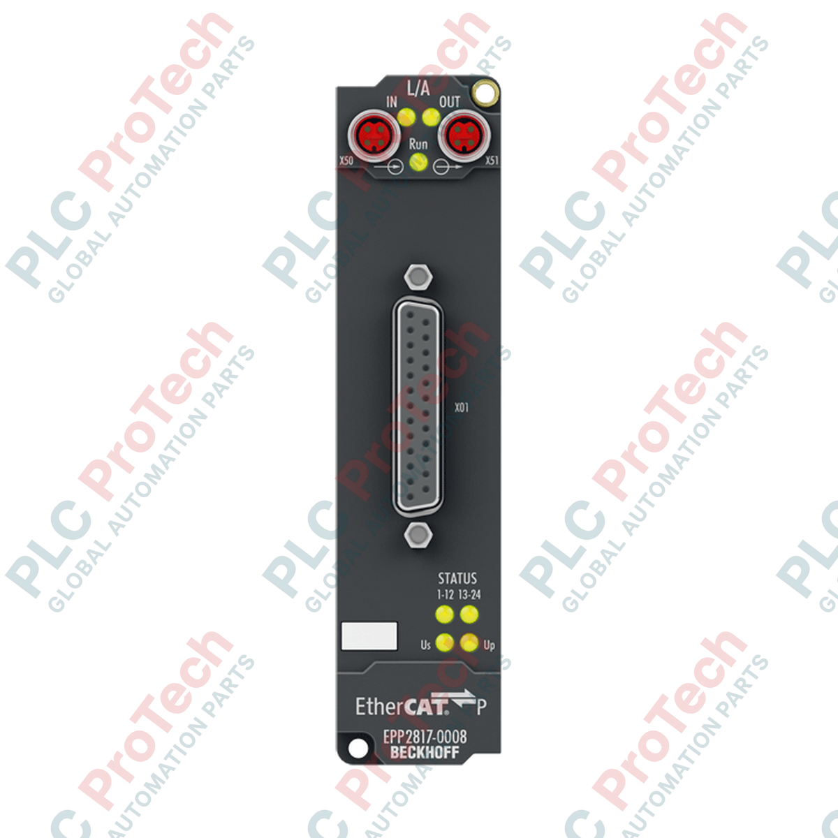
Optimized for space-constrained, decentralized automation architectures, the Beckhoff EPP2817-0008 provides a high-density digital output interface directly in the field without requiring an electrical enclosure. This ruggedized EtherCAT P Box module incorporates 24 digital outputs in a single housing, utilizing a compact 25-pin D-sub interface to distribute power to actuators, contactors, and indicators. By utilizing EtherCAT P technology, the unit integrates ultra-high-speed data transmission and dual 24 V DC power supplies (US for control voltage and UP for peripheral load voltage) into a single, standardized P-coded M8 connection, dramatically reducing cabling complexity, weight, and installation footprints.
Key Features
-
High Density I/O: 24 digital outputs packed into a highly compact, IP67-rated form factor.
-
One-Cable Automation: EtherCAT P technology combines communication and system/load power into one P-coded M8 line.
-
Short-Circuit Protection: Each channel is individually protected against short circuits, limit-tested at 1.0 A maximum peak current.
-
Integrated Diagnostics: Dedicated hardware monitoring detects undervoltage conditions below 18 V DC for both US and UP supply lines.
-
Distributed Clocks: Native EtherCAT Distributed Clocks support ensures precise output synchronization with fast switching dynamics.
-
Severe Environment Protection: Fully encapsulated IP65, IP66, and IP67 protection classes make the module resistant to dust, moisture, and high-pressure washdowns.
Industrial Applications
- Modular assembly machinery and robotic end-of-arm tooling.
- Decentralized conveyor systems, sorting systems, and material handling lines.
- Packaging machinery requiring distributed valve terminal and actuator controls.
- Automotive assembly lines and tooling systems exposed to high vibration.
Technical Specifications
| Parameter |
Specification Value |
| Manufacturer |
Beckhoff Automation |
| Model Reference |
EPP2817-0008 |
| Communication Protocol |
EtherCAT P |
| Bus Interface |
2 x M8 socket, shielded, screw type, P-coded (Upstream/Downstream) |
| Number of Digital Outputs |
24 |
| Output Connection Type |
D-sub socket, 25-pin, UNC4-40 mounting thread |
| Permissible Load Types |
Ohmic (resistive), inductive, lamp load |
| Nominal Output Voltage |
24 V DC (-15% / +20%) |
| Maximum Output Current |
0.5 A per channel (short-circuit proof), 3.0 A cumulative sum max |
| Switching Execution Speed |
Typical Turn-on (TON): 10 us | Typical Turn-off (TOFF): 50 us |
| Short-Circuit Current Limit |
Maximum 1.0 A peak per channel |
| Current Consumption (from US) |
Typical 100 mA |
| Auxiliary Power Current (from UP) |
Typical 20 mA + connected load current |
| Electrical Isolation |
500 V RMS (test voltage) |
| Operating Temperature Range |
-25 to +60 degC |
| Storage Temperature Range |
-40 to +85 degC |
| Vibration/Shock Resistance |
Conforms to EN 60068-2-6 / EN 60068-2-27 |
| EMC Immunity and Emission |
Conforms to EN 61000-6-2 / EN 61000-6-4 |
| Environmental Protection Rating |
IP65 / IP66 / IP67 (conforms to EN 60529) |
| Standards and Approvals |
CE, UL |
| Net Weight |
0.165 kg (approx. 165 g) |
| Shipping Weight (Calculated) |
0.500 kg |
Connections and Interfaces
| Connector Port |
Physical Type |
Functional Assignment |
| EtherCAT P Input |
M8, 4-pin socket, P-coded |
Incoming EtherCAT communication, US system/sensor power, UP load/actuator power |
| EtherCAT P Output |
M8, 4-pin socket, P-coded |
Outgoing EtherCAT communication and power daisy-chain to downstream EPP modules |
| Digital Outputs (1 to 24) |
25-pin D-sub socket, UNC4-40 |
Pin 1 to 24: Digital Output Channels | Pin 25: Common Ground (GND) |
Alternative Models and Compatibility
The EPP2817-0008 represents the advanced EtherCAT P single-cable variant of the standard EP2817 multi-cable systems. Note that standard EtherCAT (EP-series, A/D-coded) and EtherCAT P (EPP-series, P-coded) cannot be interconnected directly without an EP9224 or EP9228 power injector/junction box. When planning hardware transitions from legacy layouts, confirm your TwinCAT system manager configurations are updated with the XML device description file (ESI) specifically generated for EtherCAT P modules.
Application Pitfalls and Engineering Notes
While individual outputs are capable of switching a nominal load of 0.5 A, system designers must rigorously observe the cumulative current budget. The maximum total sum current of the module is strictly capped at 3.0 A due to structural thermal constraints within the IP67 housing. Operating the module above this limit will trigger thermal protection and localized shut-downs. Additionally, because inductive loads generate inverse EMF voltage spikes, external freewheeling diodes should be used on high-inductance solenoids to preserve switching life, despite internal clamping protective circuits.
Commissioning and Wiring Tips
To maintain maximum electromagnetic compatibility (EMC) in harsh industrial environments, always use fully shielded 25-pin D-sub mating cables with the outer shield terminated to the metallic D-sub shell backshell. Ensure that the M8 P-coded locking nuts are tightened using a calibrated torque wrench (typically 0.4 Nm) to guarantee the IP67 rating and avoid continuous micro-interruptions in high-vibration applications.
Installation Guidelines
CRITICAL WARNING: Completely de-energize the entire segment of the EtherCAT P network, including both control voltage (US) and peripheral power supply (UP), prior to mating or unmating any electrical connection. Plugging or unplugging the M8 P-coded or 25-pin D-sub connectors under load can result in permanent contact degradation, electrical arcing, and internal component damage.
-
1
Mount the module securely on an even mounting surface using M3 bolts through the mounting holes on the top and bottom flanges. Do not exceed 0.8 Nm tightening torque on the mounting bolts.
-
2
Connect the shielded 25-pin D-sub actuator wiring cable. Tighten the UNC4-40 retention screws thoroughly to provide correct mechanical strain relief and ensure an IP67 seal.
-
3
Thread and secure the incoming EtherCAT P M8 cable (P-coded) from the master controller or previous node to the input port. Torque the M8 ring to 0.4 Nm.
-
4
Apply system power and verify link statuses utilizing the integrated LED indicators for EtherCAT link status (L/A) and voltage status (US/UP).