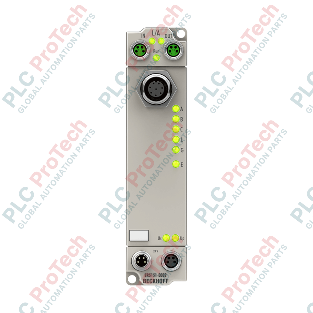
Description
Direct field-level installation without an electrical cabinet is made seamless with the Beckhoff ER5151-0002, a high-performance EtherCAT Box designed for direct connection to incremental encoders. This module functions as an interface for differential physical signals (RS422) or single-ended TTL signals, providing precise, real-time position and frequency acquisition directly on the machine. Featuring a ruggedized, fully-sealed housing, the ER5151-0002 delivers high-speed counter processing and integrated Distributed Clocks (DC) support to ensure microsecond-level synchronization across your industrial EtherCAT network.
Features
-
Multi-Interface Technology: Supports differential RS422, single-ended TTL, counter, and pulse generator modes in a single channel.
-
High-Speed Counter: Dynamic 16/32-bit switchable counter with a limit frequency of up to 4 million increments per second under 4-fold evaluation.
-
Robust Field Design: Enclosed in a zinc die-cast housing with IP65, IP66, and IP67 ratings for reliable operation under extreme environmental stress.
-
Precise Synchronization: Built-in Distributed Clocks (DC) guarantee highly accurate synchronization with other EtherCAT devices.
-
Short-Circuit Protection: Integrated 24 V DC sensor supply rated up to 0.5 A, featuring full short-circuit defense.
Applications
-
Decentralized Motion Control: Real-time position feedback from servo axes and rotary encoders directly on the machine frame.
-
High-Speed Part Tracking: Count and latch verification systems on sorting, packaging, and conveyor lines.
-
Heavy-Duty CNC Machining: Dynamic feedback loop integration in wet, dusty, or high-vibration machining centers.
Technical Specifications
| Parameter |
Specification Value |
| Manufacturer |
Beckhoff Automation |
| Model Identifier |
ER5151-0002 |
| Communication Protocol |
EtherCAT |
| Bus Interface |
2 x M8 socket, shielded, screw type |
| Encoder Connection |
M12, screw type, 8-pin |
| Power Supply Connection |
Feed: 1 x M8 male, 4-pin; Downstream: 1 x M8 female, 4-pin |
| Nominal Operating Voltage |
24 V DC (-15% / +20%) |
| Current Consumption (from US) |
Typical 130 mA + load |
| Sensor Power Supply |
24 V DC / 0.5 A, short-circuit proof |
| Electrical Isolation |
500 V |
| Limit Frequency |
4 MHz (with 4-fold evaluation) |
| Operating Temperature |
0 to +55 degC |
| Storage Temperature |
-25 to +85 degC |
| Protection Class |
IP65 / IP66 / IP67 (conforms to EN 60529) |
| Net Weight |
265 g |
| Shipping Weight (Calculated) |
0.50 kg |
| Country of Origin |
Germany |
Empirical Engineering Insights
Alternative Models & Compatibility
The ER5151-0002 serves as the ruggedized, IP67 machine-mountable equivalent of the cabinet-bound EL5151 EtherCAT Terminal. It shares identical registers, process data structures, and TwinCAT configuration paths. Existing configurations inside TwinCAT 2.x and TwinCAT 3.x can be transitioned with minimal adjustment by mapping the target IO to the ER5151-0002 box instead of the EL5151 terminal module.
Application Pitfalls & Engineering Notes
When utilizing single-ended TTL encoders or 24V HTL configurations, ensure that the common ground loop is strictly controlled. Floating encoder grounds on field machinery can induce common-mode voltages that exceed the 500 V optical isolation barrier, risking damage to the internal logic circuitry. Additionally, monitor power-loop dissipation: the combined power draw of the box logic, encoder, and downstream modules on the M8 T-junction must not exceed 4 A.
Commissioning & Wiring Tips
Always employ fully shielded M12 8-pin cordsets for the encoder interface. Under high noise profiles (e.g., when routed near variable frequency drive cables), connect the cable shield 360 degrees to the metallic connector knurling. The zinc die-cast housing of the ER5151 must be grounded to the machine frame via a low-impedance connection (use a tooth washer on the mounting ear to cut through oxide or paint layers).
Installation Guidelines
CRITICAL WARNING: De-energize all primary 24 V DC power supplies prior to mating or unmating the M8 and M12 fieldbus connections. Hot-plugging sensor inputs in wet or high-humidity conditions can cause localized arcing, leading to physical pin degradation and unexpected diagnostic errors.
-
1
Mount the module to a flat metal surface using two M4 screws. Ensure direct metal-to-metal contact for optimized EMC grounding and auxiliary thermal dissipation.
-
2
Connect the incoming and outgoing EtherCAT lines to the M8 sockets. Securely torque the screw connectors to verify IP67 ingress seals are maintained.
-
3
Plug the M12 8-pin encoder cable into the sensor socket, ensuring proper keying. Hand-tighten until the knurling is flush to prevent water intrusion.
-
4
Power on the system and scan the EtherCAT network via TwinCAT System Manager to initiate box configuration.