Description
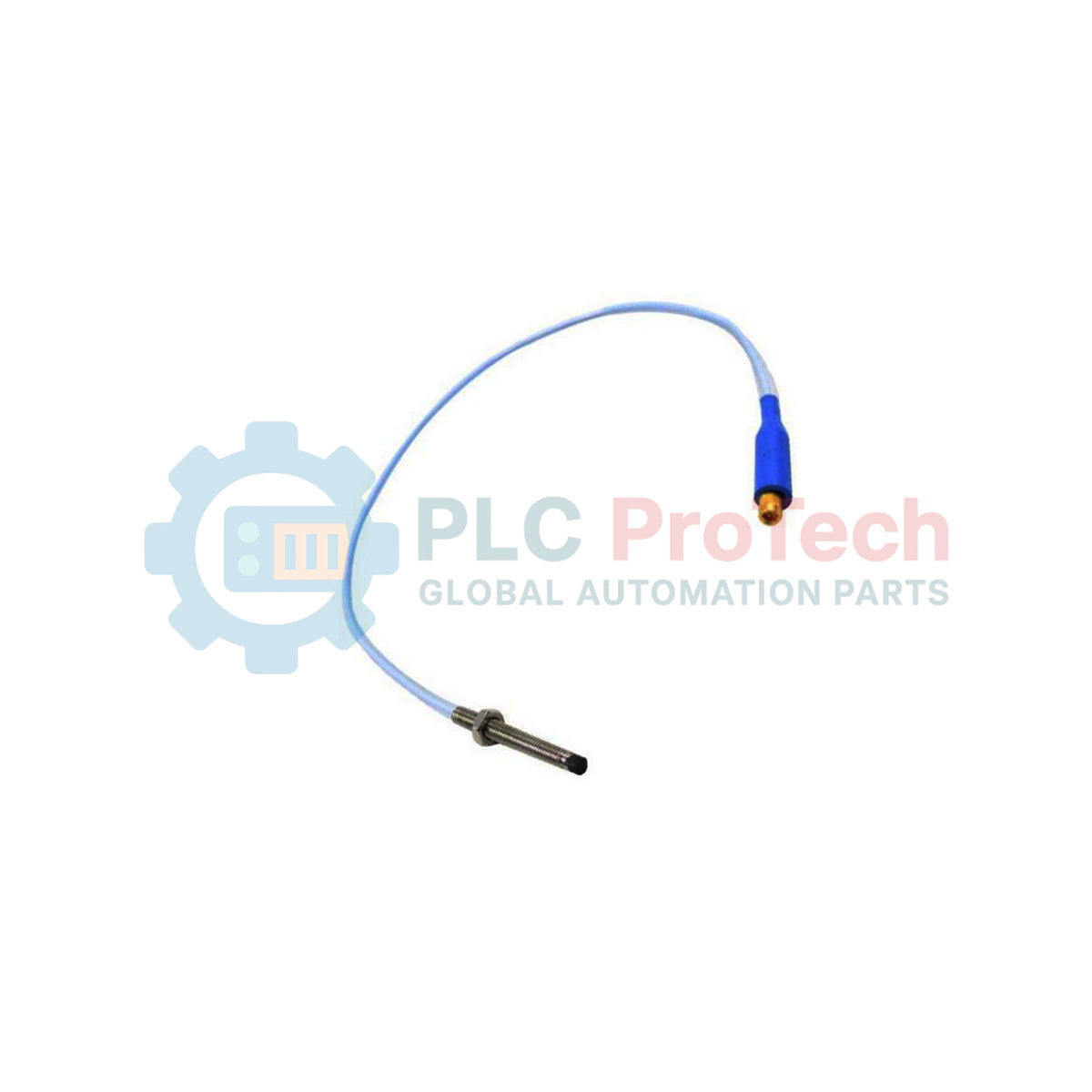
Designed to monitor radial vibration and axial position in space-constrained machinery, the Bently Nevada 330901-00-15-70-02-CN is an industrial-grade proximity probe belonging to the specialized 3300 NSv series. This sensor is engineered for applications with small target diameters or limited installation clearances, operating with a 75 ohms coaxial fluoroethylene propylene (FEP) insulated cable. Featuring an unthreaded length of 0.0 inches, an overall case length of 1.5 inches, and a total cable length of 7.0 meters (23.0 feet), this system is terminated with a miniature coaxial ClickLoc connector to ensure reliable connection integrity in demanding industrial environments.
Features
- Optimized probe tip geometry designed specifically for small shaft targets and tight radial clearances.
- Corrosion-resistant AISI304 stainless steel probe case suited for harsh fluid environments.
- Polyphenylene sulfide (PPS) probe tip material providing robust protection against mechanical wear and chemical exposure.
- Integrated ClickLoc miniature coaxial connector ensures a stable, moisture-resistant electrical connection.
- Highly durable fluoroethylene propylene (FEP) cable insulation offering excellent thermal stability and chemical resistance.
Applications
- Radial vibration and axial thrust measurements on small-diameter, high-speed rotating shafts.
- Fluid-film bearing clearance monitoring in compact auxiliary pumps, blowers, and turbo-expanders.
- Machinery protection and condition monitoring within petrochemical refineries, power generation facilities, and gas processing plants.
- Enclosed industrial gearboxes and high-speed turbocompressors with restricted mounting space.
Technical Specifications Table
| Parameter |
Specification |
| Manufacturer |
Bently Nevada |
| Model Number |
330901-00-15-70-02-CN |
| Probe Series |
3300 NSv |
| Unthreaded Length |
0.0 in |
| Overall Case Length |
1.5 in |
| Total Length |
7.0 meters (23.0 feet) |
| Connector and Cable Type |
Miniature coaxial ClickLoc connector, standard cable |
| Cable Impedance |
75 ohms coaxial |
| Cable Insulation |
Fluoroethylene propylene (FEP) |
| Probe Case Material |
AISI304 stainless steel (SST) |
| Probe Tip Material |
Polyphenylene sulfide (PPS) |
| Agency Approval Option |
CN (Country-specific hazardous area approvals) |
| Country of Origin |
United States |
| Shipping Weight |
1.5 kg |
Empirical Engineering Insights
Alternative Models & Compatibility: The 3300 NSv probe is highly specialized and is designed exclusively for use with the 3300 NSv Proximitor Sensor. It cannot be combined with standard 3300 XL 5mm, 8mm, or 11mm Proximitor sensors. Intermixing mismatched probes and sensors shifts the RF field tuning, leading to severe measurement error, non-linear output, or complete system calibration failure.
Application Pitfalls & Engineering Notes: Because the NSv system is optimized for small-diameter targets, it is exceptionally sensitive to magnetic and mechanical runout (scratches, dents, material inconsistencies) on the shaft target area. Ensure the shaft target surface is ground, polished, and demagnetized to minimize electrical runout signals that the system could misinterpret as actual shaft vibration.
Commissioning & Wiring Tips: When routing the 7.0-meter integrated probe cable, respect the minimum bend radius specifications to avoid damaging the internal coaxial shielding. Use specialized ClickLoc connector tools during final connection, and ensure the connector joint is insulated with self-amalgamating tape or silicone sleeves if moisture or oil splash is present at the junction box.
Installation Guidelines
CRITICAL WARNING: Completely isolate and lock out all machinery power sources before commencing installation. Ensure the monitored shaft is completely static. Disconnect power to the proximity sensor loop to prevent accidental electrical short circuits or electrostatic discharges during handling.
1
Inspect the probe tip and threaded body for physical damage. Clean the mounting port threads thoroughly to ensure free and smooth thread movement.
2
Thread the probe into the mounting bracket or casing by hand until the tip lightly contacts the shaft target. Measure the physical distance using standard mechanical depth micrometers if direct contact is restricted.
3
Back off the probe to establish the recommended mechanical gap (typically matching the electrical calibration midpoint of the Proximitor sensor, monitored via DC voltage output at the Proximitor OUT terminal).
4
Secure the probe using the locknut, ensuring the probe does not rotate during final tightening. Route the standard FEP cable back to the junction box through a dedicated, grounded protective conduit.