Description
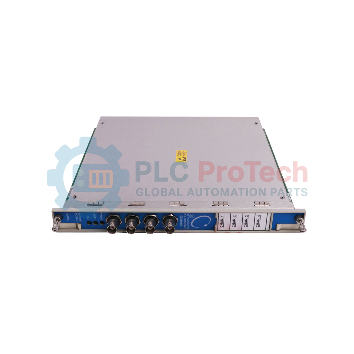
Accepting input from various proximity, rotary, and linear displacement transducers, the Bently Nevada 3500/45-01-00 functions as a highly reliable 4-channel position monitor within the 3500 Series machinery protection architecture. This specific model features the 01 I/O module configuration, which integrates internal terminations specifically designed to interface directly with Proximitor sensors, Rotary Potentiometric Transducers (RPT), and DC Linear Variable Differential Transformers (DC LVDT) without requiring external terminal blocks. It processes physical displacement signals to continuously evaluate asset health, comparing measured values against user-configured alarm setpoints to drive automated machinery shutdown systems and prevent catastrophic failures.
Key Features
-
Four-Channel Monitoring: Processes up to four independent transmitter signals simultaneously for multi-point position tracking.
-
Internal Termination Board: The -01 option provides integrated wiring termination points, reducing cabinet footprint and installation labor.
-
Versatile Sensor Compatibility: Direct integration with standard proximity probes, linear position sensors (LVDT), and rotary pots.
-
Onboard Machinery Protection: Continuously compares active readings against Alert and Danger limits to trigger relay outputs.
-
Comprehensive Self-Diagnostics: Constant monitoring of transducer circuit integrity, power status, and internal hardware faults.
Industrial Applications
- Steam turbine control valve and governor position monitoring.
- Gas turbine casing thermal expansion tracking.
- Hydroelectric generator thrust collar axial displacement monitoring.
- Heavy industrial compressor and pump shaft axial position defense.
Technical Specifications
| Parameter |
Specification Value |
| Manufacturer |
Bently Nevada (Baker Hughes) |
| Model Series |
3500 Series Machinery Protection System |
| Part Number / SKU |
3500/45-01-00 |
| I/O Module Type |
Position I/O Module with Internal Terminations (Proximitor, RPT, DC LVDT) |
| Agency Approvals |
00 = None (Standard Industrial Grade) |
| Operating Temperature |
-30 degC to +65 degC (-22 degF to +150 degF) |
| Storage Temperature |
-40 degC to +85 degC (-40 degF to +185 degF) |
| Relative Humidity |
95% non-condensing |
| Rack Space Requirements |
1 full-height front slot (requires matching rear I/O card) |
| Dimensions (H x W x D) |
24.13 cm x 2.44 cm x 24.18 cm (9.50 in x 0.96 in x 9.52 in) |
| Net Weight |
0.91 kg (2.0 lbs) |
| Shipping Weight (Calculated) |
2.0 kg (4.4 lbs) |
| Country of Origin |
United States of America |
Empirical Engineering Insights
Alternative Models & Compatibility
The 3500/45-01-00 is hardware-coded for internal terminations. If your installation utilizes external termination blocks or bussed external termination structures, you must source the 3500/45-02-XX version instead. When swapping cards within an active 3500 rack, ensure the backplane firmware is updated to support version changes, as older backplane revisions may require a software-driven channel-mapping update via the 3500 Rack Configuration Software.
Application Pitfalls & Engineering Notes
A common failure point in DC LVDT integrations is sensor power overload. While the -01 internal termination I/O module provides DC excitation voltage, the cumulative current draw of four high-power active LVDTs can stress the module's onboard power regulators. If utilizing long field cables or high-current sensors, measure the loop impedance carefully to prevent thermal stress on the I/O card, which typically results in intermittent "Not OK" channel diagnostic faults.
Commissioning & Wiring Tips
Ensure that all sensor shields are terminated only at the designated instrument ground terminal on the 3500/45 I/O module. Do not ground the shield at the sensor end, as this creates a ground loop capable of inducing noise on the high-impedance displacement signal. When performing zero and span calibration for RPTs or LVDTs, verify that the mechanical linkage is fully coupled to the machine element before running the configuration wizard to avoid clipping the high or low signal thresholds.
Installation Guidelines
CRITICAL WARNING: Never insert or remove the 3500/45 monitor or its companion I/O module while the 3500 rack is powered. Live-swapping these modules without putting the rack into "Bypass" mode can cause false trip signals on adjacent protection loops and damage highly sensitive surface-mount components on the backplane interface.
1
De-energize the main rack power supply and secure the field wiring loops by putting active machinery trip relays into the "Bypass" state.
2
Slide the main 3500/45 processing module into the designated front rack slot, ensuring the card guide rails align precisely before firmly seating the connector.
3
Install the -01 Internal Termination I/O Module into the corresponding slot on the rear of the rack and secure all chassis mounting screws.
4
Connect field wiring to the terminal block, verifying the pinouts for Proximitor, RPT, or LVDT interfaces against the engineering print before applying power.