Description
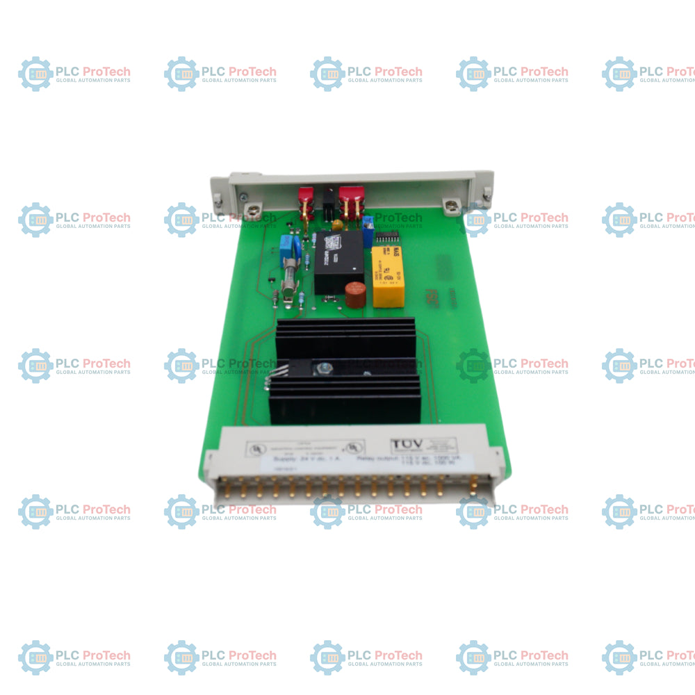
Integrating directly into Honeywell Fail Safe Control (FSC) and Safety Manager architectures, the Honeywell 10310/2/1 functions as a specialized DC earth leakage detector to monitor insulation degradation and ground faults. This module continuously evaluates DC distribution systems to detect active ground faults before they escalate into systemic failures or hazardous plant shutdowns. Operating on a nominal 24 VDC power supply, the unit maintains a balanced earth reference of -12 VDC under normal, non-fault operating conditions. Any electrical current imbalance on the DC loop is registered by the internal monitoring circuitry, triggering an output relay once the current leakage exceeds a predefined threshold limit.
Key Features
-
Continuous DC Supervision: Real-time insulation integrity monitoring of balanced 24 VDC power networks.
-
Multi-Mode Frequency Switching: Selectable DC mode for operational monitoring alongside 1 Hz and 0.25 Hz pulsed modes for pinpointing localized earth faults.
-
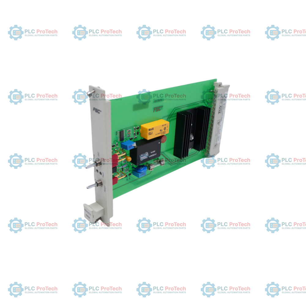
Integrated Self-Test Capability: Front-accessible manual test function allows validation of physical loop integrity and output relays.
-
Dual Reset Controls: Supports both local manual reset and remote reset integration via designated 24 VDC or 110 VAC inputs.
-
Front-Panel Diagnostics: High-visibility LED indicator displays live status variations and selected test pulse frequencies.
Applications
- Emergency Shutdown Systems (ESD) and safety-critical process networks.
- Petrochemical, oil and gas, and refining safety management platforms.
- High-availability DC auxiliary power panels in heavy utility generation plants.
Technical Specifications
| Parameter |
Value / Specification |
| Manufacturer |
Honeywell |
| Model Number |
10310/2/1 |
| System Compatibility |
Fail Safe Control (FSC) / Safety Manager |
| Nominal Supply Voltage |
24 VDC |
| Operating Voltage Range |
18 VDC to 30 VDC |
| Normal Earth Reference |
-12 VDC |
| Leakage Trip Threshold |
5.5 mA +/- 1 mA |
| Signal Outputs |
Dry contact relay output |
| Contact Power Rating |
1 A at 115 VAC or 100 W at 24 VDC |
| Operating Pulse Frequencies |
DC (Normal), 1.0 Hz (Fast), 0.25 Hz (Slow tracing) |
| Mounting Configuration |
DIN rail or FSC Rack Interface (Slot positions A5, A11) |
| Shipping Weight (Calculated) |
1.5 kg |
| Package Dimensions (Calculated) |
180 mm x 120 mm x 60 mm |
Connections and Interfaces
| Interface Type |
Electrical Assignment |
| Rst24 Terminal |
Remote manual reset input via standard 24 VDC signal pulse |
| Rst110 Terminal |
Remote manual reset input via high-voltage 110 VAC signal pulse |
| Relay Contact Blocks |
Potential-free changeover contact for remote DCS or Safety Manager fault registration |
Empirical Engineering Insights
Alternative Models & Compatibility
The 10310/2/1 is engineered specifically for Safety Manager and Fail Safe Control (FSC) hardware revisions. While physical slide-in mounting fits standard A5 and A11 slot matrices, verify existing system bus revisions to ensure backplane compatibility with remote software reset calls.
Application Pitfalls & Engineering Notes
During heavy inductive switching or when system lines feature highly distributed cable lengths, parasitic capacitance can induce transient currents. This dynamic capacitive charging can cause nuisance tripping near the 5.5 mA leakage threshold. Segment the DC distribution if line capacitance consistently breaches typical operational limits.
Commissioning & Wiring Tips
When utilizing the low-frequency 0.25 Hz pulsed mode to locate localized earth faults in the field, use a low-frequency current clamp paired with a high-impedance digital multimeter. Standard clamp-on sensors often register 0.25 Hz pulses as thermal drift, yielding incorrect readings.
Installation Guidelines
CRITICAL WARNING: De-energize and lock out all upstream DC power distribution systems before executing physical installation. Do not ground or jumper the reference earth terminal during operations, as accidental reference shorts can damage the internal sensing circuits of adjacent control modules in the FSC rack.
1
Install the module into the designated DIN rail mounting space or securely slide it into position within designated FSC rack slots (A5 or A11).
2
Connect the 24 VDC primary power supply lines and secure the dedicated earth ground reference wiring to the local terminal strip.
3
Integrate the relay contact monitoring connections directly into the safety system's functional alarm logic inputs.
4
Activate control system power and press the front manual test button to confirm real-time system alarm actuation and relay health.