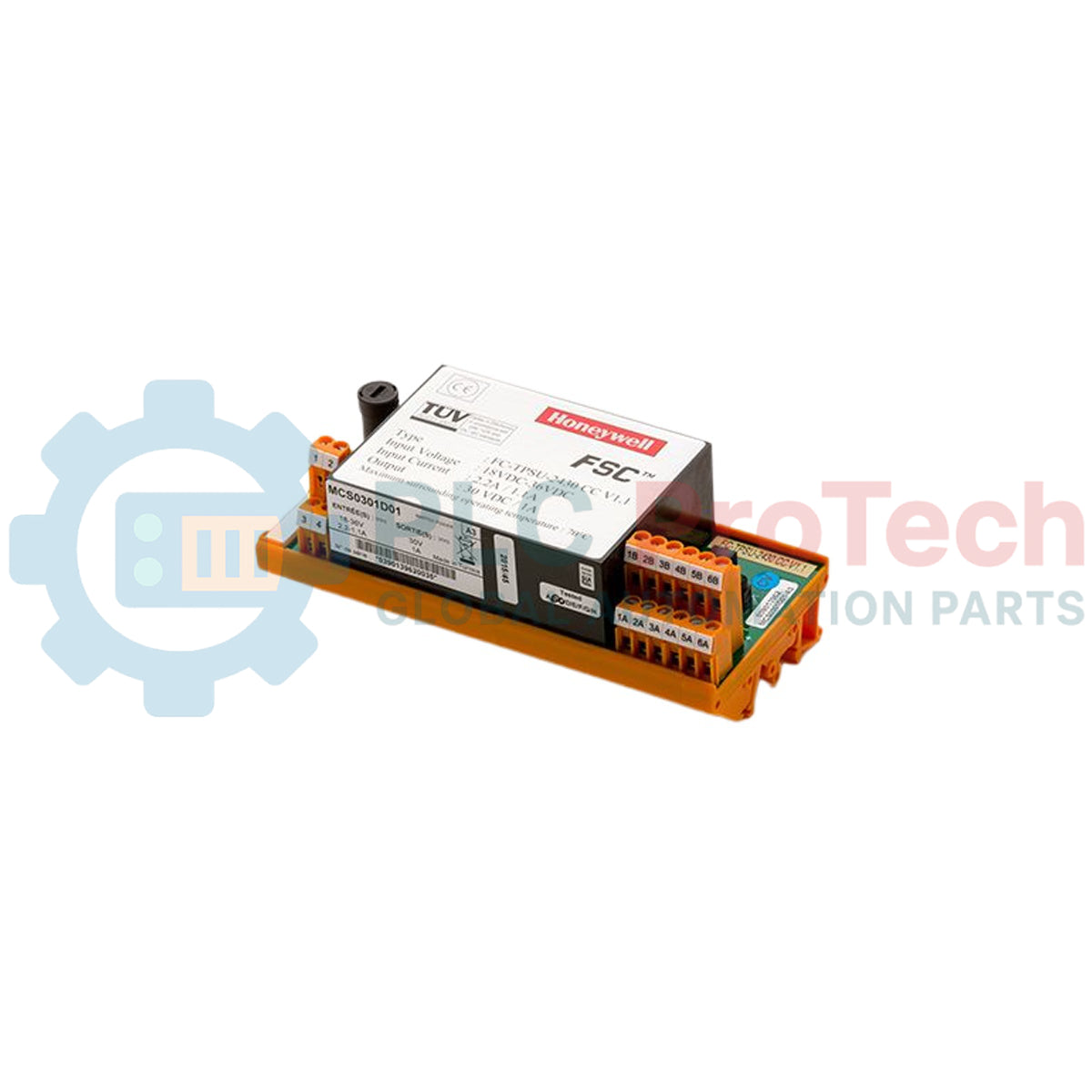
Description
Designed to deliver regulated DC power within critical control architectures, the Honeywell FC-TPSU-2430 serves as a high-reliability power supply module for Safety Manager systems. This safety-instrumented module supplies stabilized 24 Vdc power to chassis backplanes, input/output channels, and field-side devices. Operating within safety-instrumented systems (SIS) up to SIL3 compliance, the module provides integrated overvoltage protection, thermal monitoring, and active current limiting to safeguard connected safety loop circuits.
Key Features
- High-efficiency 24 Vdc regulation optimized for Safety Manager system backplanes.
- Integrated diagnostic monitoring for under-voltage, over-temperature, and current overload conditions.
- Robust diagnostic feedback integrated directly into Safety Manager system software for real-time status reporting.
- Hot-swappable physical form factor supporting continuous uptime during module servicing or replacement.
Applications
- Emergency Shutdown (ESD) systems in petrochemical, refining, and gas processing operations.
- Fire and Gas (F&G) system loop power distribution networks.
- Burner Management Systems (BMS) in industrial boiler plants and high-temperature furnaces.
- Critical control loop isolation and power supply in SIL3 rated processes.
Technical Specifications
| Parameter |
Specification Value |
| Manufacturer |
Honeywell |
| Model Code |
FC-TPSU-2430 (FCTPSU2430) |
| System Compatibility |
Honeywell Safety Manager / Safety Manager SC |
| Output Voltage (Nominal) |
24 Vdc |
| Output Current Rating |
30 A |
| Safety Integrity Level |
Capable of SIL3 configurations |
| Operating Temperature Range |
0 to 60 Celsius (non-condensing) |
| Storage Temperature Range |
-40 to 85 Celsius |
| Shipping Weight (Calculated) |
3.00 kg (6.61 lbs) |
| Package Dimensions (Calculated) |
31.0 cm x 15.0 cm x 8.0 cm (12.2 in x 5.9 in x 3.1 in) |
Empirical Engineering Insights
Alternative Models & Compatibility
The FC-TPSU-2430 is built specifically to integrate with standard Honeywell Safety Manager backplane chassis. When replacing legacy power systems, ensure that local controller firmware is updated to register the active power monitoring telemetry sent by the newer TPSU power modules.
Application Pitfalls & Engineering Notes
In dual-redundant safety setups, verify that the load balancing factor remains under 45 percent per module. If one power source fails, the remaining module must instantly absorb the secondary load without triggering thermal trip thresholds inside compact, unventilated enclosures.
Commissioning & Wiring Tips
Before inserting the module into a live Safety Manager rack, verify backplane guide pins are aligned perfectly to prevent transient arcing. Ensure heavy-gauge grounding straps are terminated correctly at the chassis grounding point to isolate common-mode noise.
Installation Guidelines
CRITICAL WARNING
Do not install or remove this module in hazardous locations while circuits are live unless the area has been thoroughly verified as non-hazardous. Ensure complete isolation of input AC or primary DC feeds prior to physical terminal handling to prevent arc flash or permanent module component degradation.
1
Isolate primary utility or bus power feeding the safety cabinet.
2
Align the module backplane connections carefully with the designated rack guide rails.
3
Slide the module smoothly into place until the faceplate connector is locked firmly, and secure the mounting screws to torque specifications.
4
Apply input power and monitor the front-panel status LEDs to ensure proper diagnostic validation.