Description
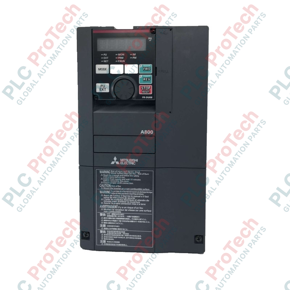
Designed for precision speed and torque control in heavy industrial environments, the Mitsubishi Electric FR-A840-00170-2-60 is a high-performance three-phase variable frequency drive belonging to the premium FR-A800 series. This standard model operates on a 400V class input and is engineered with an SLD (Super Light Duty) rated current rating of 17 A. To ensure long-term reliability in harsh operational environments, the unit features a specialized protective conformal circuit board coating (Class 3C2) without plated conductors, providing superior resistance to corrosive gases and moisture. Its robust cooling system relies on forced air circulation to maintain optimal thermal conditions inside enclosed electrical cabinets.
Features
- Advanced Real Sensorless Vector Control and Vector Control capabilities for precise speed and torque regulation.
- Specially coated circuit boards (conforming to IEC 60721-3-3 Class 3C2) for enhanced environmental resistance.
- Dual-loop PID control and built-in PLC functionality to handle localized automation sequences.
- Flexible overload capacity modes enabling optimization for various industrial load profiles.
- Integrated safety stop function complying with EN ISO 13849-1 Category 3 / PLd and IEC 60204-1.
- Forced air cooling system designed with long-life cooling fans for minimized maintenance overhead.
Applications
-
Conveyor Systems: Precise speed control and torque limits for high-inertia material handling applications.
-
Pumping and Ventilation: Energy-efficient flow control and pressure regulation using integrated PID algorithms.
-
Extruders and Mixers: High starting torque capabilities and excellent speed stability under fluctuating loads.
-
Hoists and Cranes: Smooth mechanical brake sequencing and load-torque matching routines.
Technical Specifications
| Parameter |
Value |
| Manufacturer |
Mitsubishi Electric |
| Model Number |
FR-A840-00170-2-60 |
| Series |
FR-A800 |
| Voltage Class |
Three-phase 400V class |
| Rated Input AC Voltage/Frequency |
Three-phase 380 to 500V AC, 50Hz / 60Hz |
| Permissible AC Voltage Fluctuation |
323 to 550V AC, 50Hz / 60Hz |
| SLD Rated Inverter Current |
17.0 A |
| Conformal Board Coating |
Standard 3C2 coating (conforms to IEC 60721-3-3) |
| Plated Conductor |
None |
| Protective Structure |
IP20 (Enclosed type) |
| Cooling System |
Forced air cooling |
| Unit Net Weight |
6.7 kg |
| Shipping Weight (Calculated) |
8.0 kg |
Empirical Engineering Insights
Alternative Models & Compatibility
This model serves as a modern replacement for the legacy FR-A740 series. While physical footprint changes are minor, the control terminal layout is optimized. Parameter configurations from older FR-A740 units can be seamlessly imported using the FR Configurator2 software utility. Always check terminal strip physical spacing if replacing an older generation drive inside a tight control panel.
Application Pitfalls & Engineering Notes
The -60 suffix specifies a 3C2 conformal board coating. This is highly recommended for wastewater, pulp and paper, or chemical processing sites. However, because this model is designed without plated conductors, it should not be exposed to severe atmospheric concentrations of chlorine or sulfur salts that exceed Class 3C2 specs. If operating under high ambient temperatures, thermal derating curves must be applied to prevent overtemperature faults (E.THT).
Commissioning & Wiring Tips
Always ensure that control signals are isolated from high-power cable runs. Keep control and power cables in separate wire trays or use shielded cables grounded at the drive end only. False ground fault trips (E.GF) can occur if leakage currents from long motor cable runs exceed the threshold; installing an output dV/dt filter or a common-mode choke will mitigate this issue during commissioning.
Installation Guidelines
CRITICAL WARNING: RISK OF ELECTRIC SHOCK AND EQUIPMENT DAMAGE. Ensure all main AC power sources are completely disconnected, locked out, and tagged out before installing or servicing this drive. Wait at least 10 minutes after disconnecting power to allow the DC bus capacitors to fully discharge. Verify zero voltage across terminals P/+ and N/- before touching any electrical terminals.
1
Enclosure Mounting: Mount the inverter vertically on a flat, non-flammable surface inside an IP20 or higher enclosure. Ensure minimum clearance distances (50 mm above and below, 10 mm on sides) to facilitate unobstructed airflow through the cooling heatsinks.
2
Power Input and Output Wiring: Connect the three-phase AC mains supply to terminals R/L1, S/L2, and T/L3. Connect the motor leads to terminals U, V, and W. Under no circumstances should input mains power be connected to the output terminals U, V, or W, as this will destroy the internal IGBT modules.
3
Grounding Connection: Connect the ground terminal of the drive securely to the system PE (Protective Earth) ground. Ground resistance must be 10 Ohms or less for 400V class installations to satisfy both safety standards and high-frequency noise suppression demands.