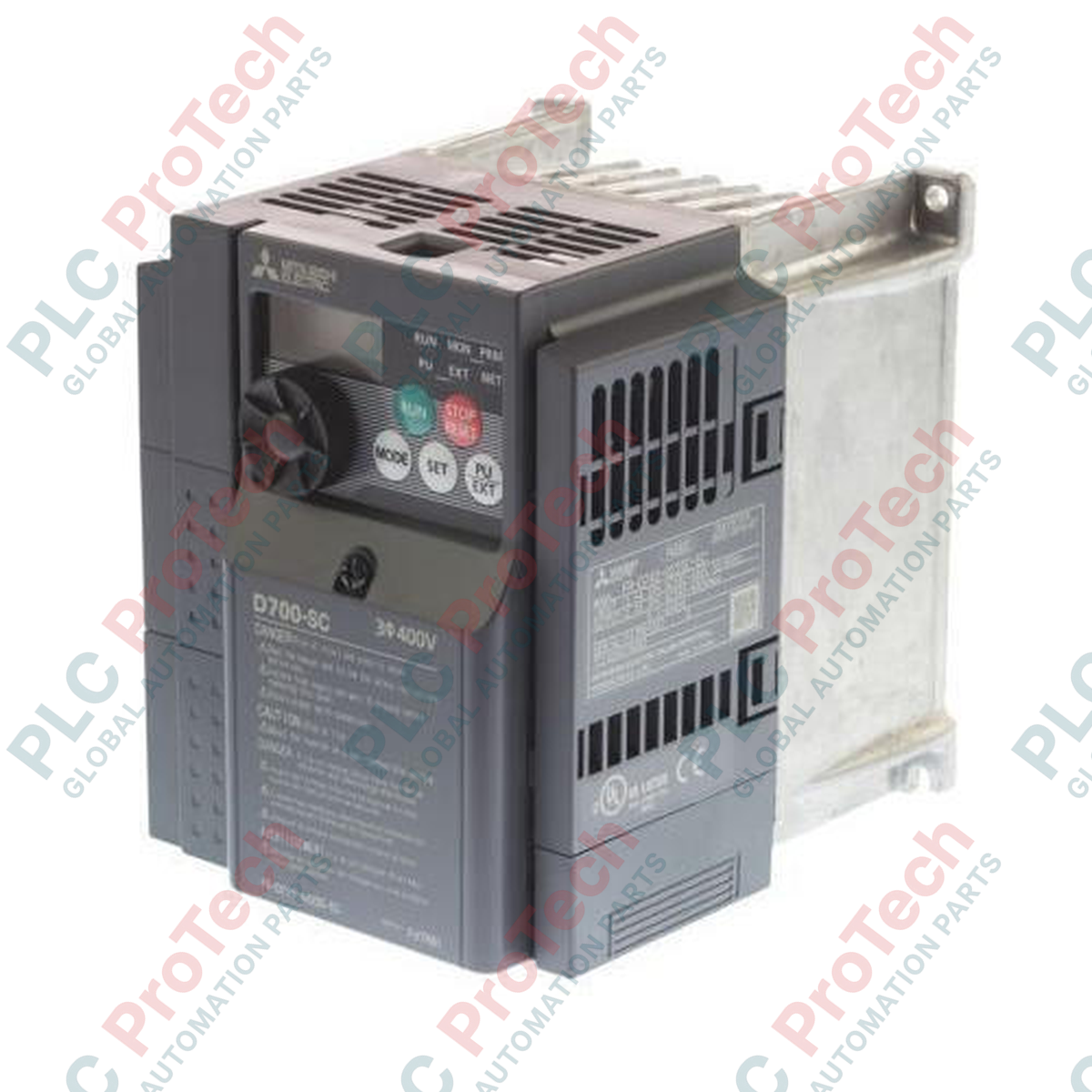
Description
Operating within high-efficiency industrial motor control systems, the Mitsubishi Electric FR-D740-022-EC variable frequency drive delivers precise speed and torque regulation for three-phase asynchronous motors. This compact micro-drive, part of the widely deployed FR-D700 Series, integrates advanced sensorless vector control to maintain 150% torque output at 1 Hz, making it suitable for demanding startup cycles. Featuring an integrated safety function conforming to ISO 13849-1 (PLd) and standard safety categories, this unit reduces total system footprint and installation complexity. The unit features built-in Modbus RTU communication, an integrated digital dial interface, and highly efficient spring clamp terminal connections optimized for longevity in heavy-vibration environments.
Key Features
-
Advanced Sensorless Vector Control: Generates high starting torque of 150% and higher at low speeds (1 Hz).
-
Embedded Safety Function: Integrated Safe Torque Off (STO) emergency stop channel minimizes secondary control circuitry.
-
Flexible Communication: Standard RJ45 port supports RS-485 Modbus RTU communications directly.
-
Braking Performance: Built-in regenerative braking transistor allows direct connection of dynamic braking resistors.
-
Industrial Enclosure: Rated IP20 protection with specialized protective varnish coating on electronic assemblies.
Applications
- Centrifugal pumps, booster systems, and ventilation fans.
- Material handling conveyors, automated packaging machines, and sorting tables.
- Gate control systems, high-speed commercial doors, and lift mechanisms.
- Small-scale industrial mixers, agitators, and auxiliary spindle drives.
Technical Specifications
| Parameter |
Specification Value |
| Manufacturer |
Mitsubishi Electric |
| Model Number |
FR-D740-022-EC |
| Series Group |
FR-D700 Series |
| Input Power Phase |
3-Phase |
| Rated Supply Voltage |
380 to 480 V AC (+/- 10% fluctuation allowance) |
| Power Frequency Range |
50 / 60 Hz (+/- 5% fluctuation allowance) |
| Motor Capacity Rating |
0.75 kW |
| Rated Output Current |
2.2 A |
| Output Frequency Range |
0.2 to 400 Hz |
| Overload Current Rating |
150% for 60 seconds, 200% for 0.5 seconds (inverse-time characteristics) |
| Enclosure Rating |
IP20 (IEC 60529 protection class) |
| Operating Ambient Temperature |
-10 to +50 degC (non-freezing) |
| Storage Temperature Range |
-20 to +65 degC |
| Physical Dimensions |
108 mm (W) x 128 mm (H) x 129.5 mm (D) |
| Net Weight |
1.2 kg |
| Shipping Weight (Calculated) |
1.6 kg |
| Packaging Dimensions (Calculated) |
150 mm x 175 mm x 185 mm |
Connections and Interfaces
| Terminal Group |
Terminal Designation |
Functional Assignment |
| Main Power Circuit |
R/L1, S/L2, T/L3 |
3-Phase AC main power supply inputs |
| U, V, W |
Output to 3-phase AC induction motor |
| P/+, PR |
Direct external dynamic braking resistor interface |
| Control Terminals |
STF, STR |
Forward Start and Reverse Start signal lines |
| RL, RM, RH |
Multi-speed selection digital inputs (Low, Medium, High) |
| SD / PC |
Control common (Sink) / 24 V DC internal external source selector reference |
| 10, 2, 5 |
Analog input voltage speed reference (10V supply, 0-10V signal, Common) |
| System Outputs |
RUN, FU |
Open collector outputs for inverter operation and frequency detection |
| A, B, C |
Relay output for fault alarm protection relay signaling (SPDT) |
Empirical Engineering Insights
Alternative Models & Compatibility
The FR-D740-022-EC is the direct European regional version utilizing spring-clamp logic connections and a default Source logic wiring scheme out of the box, distinct from the legacy screw-terminal FR-S540 family. Users replacing Japanese-market versions (FR-D740-0.75K) should note that default parameter designations for terminal configurations must be cross-checked, as the "-EC" model has built-in defaults preconfigured for European motor standard configurations.
Application Pitfalls & Engineering Notes
When utilizing this drive within side-by-side configurations in tight enclosures, ensure the environmental air-bleed structures are not blocked. Zero-clearance side-by-side mounting is valid up to 40 degC ambient temperature; however, if the local cabinet exceeds 40 degC, the drives must be spaced a minimum of 10 mm apart, or the motor current must be derated by 10%. Avoid running unshielded cable lines longer than 30 meters between the drive output (U, V, W) and the induction motor to suppress common-mode leak currents and motor-insulation degradation.
Commissioning & Wiring Tips
Before programming, verify parameter Pr. 160 is set to "0" to enable full parameter group configurations; otherwise, only basic parameter sets are editable. For multi-drop RS-485 applications, the standard RJ45 plug layout requires a 100-Ohm termination resistor across pin 3 (RDA) and pin 6 (RDB) at the physically final drive on the network segment. Ground the motor chassis directly to the inverter chassis grounding lug to mitigate EMI interference issues on neighboring analog instruments.
Installation Guidelines
CRITICAL ELECTRICAL SAFETY WARNING
Do not perform maintenance or physical wiring steps while main incoming AC power is active. After shutting down incoming power lines, wait a minimum of 10 minutes for internal high-voltage DC bus capacitors to completely discharge. Confirm that voltage levels measured between positive and negative terminals (P/+ and N/-) have decreased to safe touch levels (under 50 V DC) using a validated digital meter before handling control wiring connections.
1
Position and mount the VFD vertically on a rigid, metallic panel plate using matching M4 screws. Ensure dynamic cooling airflow clearance of at least 50 mm above and below the cooling heatsink housing.
2
Terminate a heavy-gauge PE grounding strap to the integrated ground lug on the lower frame before configuring the mains incoming or output terminal connections.
3
Route phase wires securely to L1, L2, and L3 inputs, and hook the output motor load lines onto terminals U, V, and W using shield clamping methods on motor feed lines.
4
Set the internal logic select switch (Source/Sink) located adjacent to the control terminals block to the proper configuration state prior to applying signal voltages.