Description
Engineered for precise motor control in demanding industrial environments, the Mitsubishi Electric FR-D740-5.5K-CHT regulates three-phase AC motors with high thermal and electrical efficiency. This micro-drive delivers a continuous 12.0 A output current and handles a rated capacity of 9.1 kVA, making it highly suitable for machine tools, conveyor belts, and process pumps. Built with an integrated digital dial and a robust cooling structure, it provides outstanding torque control and integrated safety options in a compact space-saving layout.
Features
-
Magnetic Flux Vector Control: Achieves reliable startup torque and smooth acceleration even under varying load conditions.
-
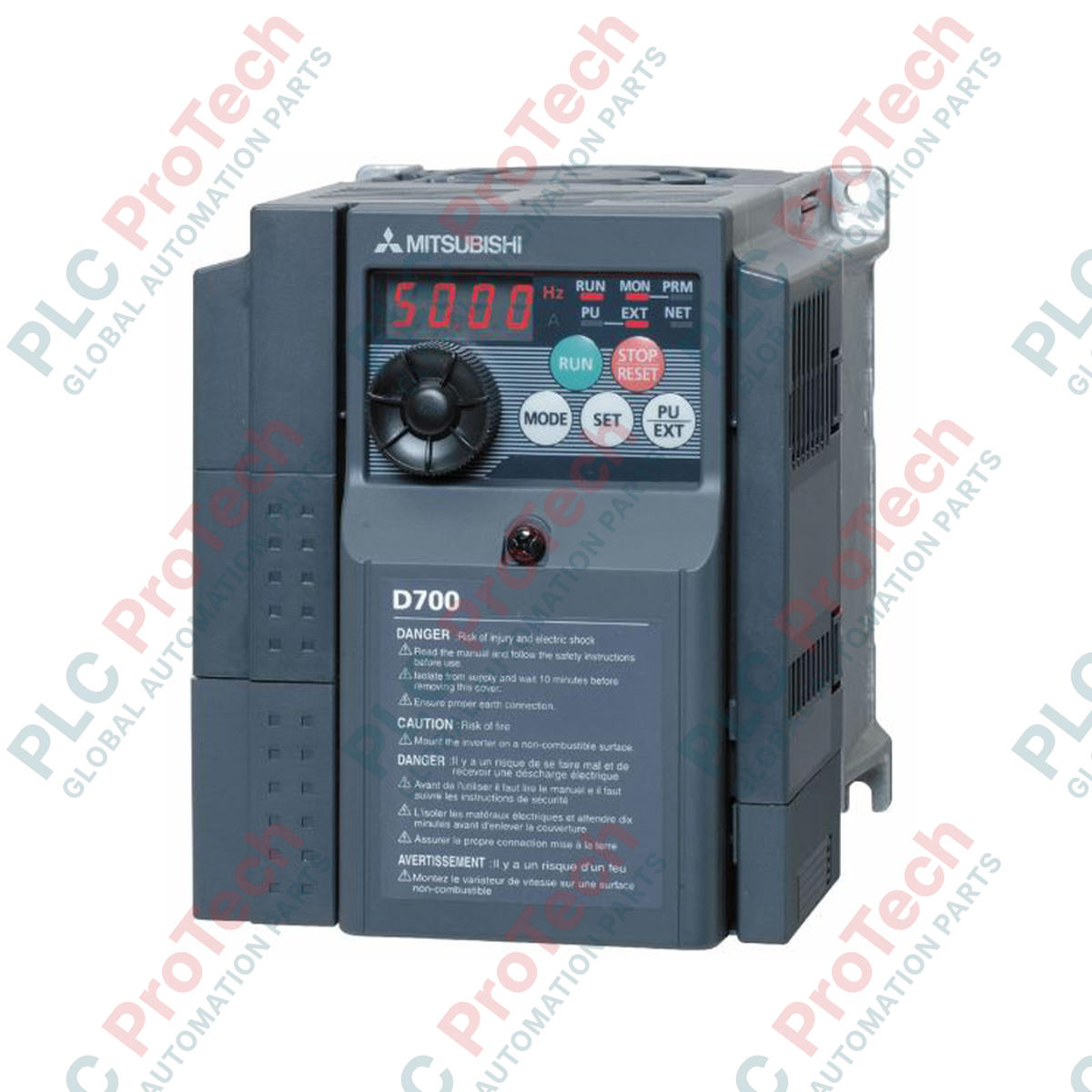
Integrated Digital Dial: Allows for rapid parameter adjustments, setpoint changes, and immediate local control.
-
Modbus RTU Communication: Embedded RS-485 port facilitates seamless communication with PLCs, HMIs, and distributed control architectures.
-
Enhanced Safety Integrity: Built-in safe torque off (STO) safety inputs comply with international machine safety guidelines.
-
Spring Clamp Control Terminals: High-vibration wiring terminals ensure continuous electrical contact without periodic retightening.
Applications
- Heavy-duty material handling conveyor lines and sorting systems.
- Industrial fan ventilation systems and centrifugal pump flow regulation.
- Woodworking machinery, packaging machines, and localized auxiliary automation panels.
Technical Specifications
| Manufacturer |
Mitsubishi Electric |
| Model Number |
FR-D740-5.5K-CHT |
| Series Name |
FR-D700 Series (FR-D740 micro-drive class) |
| Voltage Class |
Three-phase 400V Class |
| Rated Input Voltage |
380 to 480 VAC (+10% / -15%), 50/60 Hz |
| Applicable Motor Output |
5.5 kW (approx. 7.5 HP) |
| Rated Capacity |
9.1 kVA |
| Rated Output Current |
12.0 A |
| Overload Current Rating |
150% of rated current for 60 seconds (inverse-time characteristics) |
| Cooling System |
Forced air cooling (with cooling fan) |
| Protective Design |
IP20 enclosed type |
| Net Weight |
3.3 kg |
| Shipping Weight (Calculated) |
5.5 kg |
Connections and Interfaces
| Terminal/Connector |
Function / Circuit Assignment |
| R/L1, S/L2, T/L3 |
Main AC power input connections (three-phase AC power supply) |
| U, V, W |
Three-phase AC output connections to the motor |
| P/+, PR |
Brake resistor connection terminals (external dynamic braking module) |
| STF, STR |
Forward start and Reverse start digital control commands |
| SD, PC |
Control circuit common and external 24 VDC power supply terminal |
| RJ-45 Port |
RS-485 physical serial port for Modbus RTU interface configuration |
Empirical Engineering Insights
Alternative Models & Compatibility
When transitioning from an older FR-S540 or FR-E540 series drive, physical dimensions vary slightly. Check mounting hole patterns as they may require retrofit plates. Additionally, parameters cannot be directly transferred from older software; use the FR Configurator software to align digital input functions, especially when working with remote start commands mapping parameter Pr. 79.
Application Pitfalls & Engineering Notes
Under heavy load or high cycling, inadequate ventilation inside electrical cabinets may lead to premature E.THT (Inverter Overload) trip events. Ensure the cabinet ambient temperature does not exceed 50 degC. When running long motor cable distances (exceeding 30 meters), high-frequency stray capacitance increases. We highly recommend installing an output AC reactor on the U/V/W terminals to mitigate line reflection and protect motor insulation from dv/dt wear.
Commissioning & Wiring Tips
To configure control wiring for sinking (NPN) or sourcing (PNP) logic, locate the physical slide switch hidden under the dynamic panel/display board cover. Ensure this switch is pushed to the correct position matching your master controller outputs before powering on. Shielded control lines must be separated from primary power lines by at least 10 cm, running in orthogonal intersections to avoid inductions and signal noise.
Installation Guidelines
CRITICAL WARNING: Verify that the main AC power input supply is disconnected and locked out. Allow at least 10 minutes after disconnecting power for internal DC bus capacitors to discharge. Confirm that the voltage across terminals P/+ and N/- is below 45 VDC using a certified digital multimeter before touching any terminals.
1
Mount the inverter vertically to a rigid metal sub-panel using four M4 mounting bolts, maintaining a minimum clearances of 50 mm on both top and bottom edges for adequate heat dissipation.
2
Connect the primary ground terminal to the system PE plate, and wire the three-phase power lines directly to terminals R/L1, S/L2, and T/L3. Connect motor phases to U, V, and W.
3
Run low-voltage control lines for emergency stops and digital commands using high-density shielded twisted-pair cables. Ground the shield at the drive terminal block only.
4
Reinstall terminal shields and front safety panel, switch on AC power, and set parameter Pr. 80 (Motor Capacity) and Pr. 9 (Electronic Thermal Overload Relay) based on the motor's nameplate rating.