Description
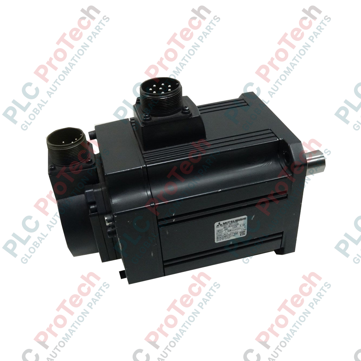
Engineered for high-torque industrial automation applications requiring exceptional mechanical reduction, the Mitsubishi Electric HC-SFS102BG1H 1/43 is an industrial-grade geared servo motor designed to deliver precise motion control under heavy loads. This unit integrates a high-performance 1.0 kW rotary servo motor from the rugged HC-SFS Series with a robust G1H leg-type reduction gear featuring a 1/43 reduction ratio. Designed for stability and reliability, this model features a built-in electromagnetic safety brake for secure vertical axis or stationary hold operations, protecting machinery from unexpected power failures.
Key Features
-
Integrated Electromagnetic Brake: Reliable 24VDC holding brake for vertical applications and load locking.
-
Industrial G1H Reduction Gearbox: Leg-mounted gear assembly with a heavy-duty 1/43 ratio, designed for high output torque at reduced operating speeds.
-
Medium Inertia Design: Provides optimal load-to-motor inertia matching, improving stabilization and performance in heavy duty systems.
-
Durable Enclosure: Designed to withstand typical industrial environments with oil and dust resilience.
Applications
- Heavy-duty conveyor and transfer lines requiring high static torque.
- Automated packaging and cartoning machinery.
- Material handling systems and multi-axis gantry positioners.
- Elevating systems and lifters requiring fail-safe holding brakes.
Technical Specifications
| Parameter |
Specification Value |
| Manufacturer |
Mitsubishi Electric |
| Model Number |
HC-SFS102BG1H 1/43 |
| Series Name |
HC-SFS |
| Rated Output |
1.0 kW |
| Base Rated Speed |
2000 r/min |
| Electromagnetic Brake |
Yes (Holding Brake Type) |
| Reduction Gear Type |
G1H (For general industrial machines, leg-type) |
| Gear Reduction Ratio |
1/43 |
| Shipping Weight |
55.0 kg |
Connections and Interfaces
| Terminal / Connector Type |
Signal Pin Out & Assignment |
| Motor Power Lead Wire |
Red (U), White (V), Black (W), Green/Yellow (Ground / PE) |
| Brake Terminals |
Blue, Blue (Dedicated 24VDC control lines, non-polarized) |
| Encoder Connector |
Dedicated plug compatibility for Mitsubishi high-resolution feedback cables |
Empirical Engineering Insights
Alternative Models & Compatibility
The HC-SFS102BG1H 1/43 is a unique, foot-mounted (leg-type) assembly. If replacing a standard flange-mounted HC-SFS102B motor, significant mechanical modifications are required as the shaft height and mounting footprint differ completely. Control parameters on MR-J2S-100A or MR-J2S-100B amplifiers must recognize the motor ID correctly via encoder feedback; verify that your drive firmware version supports the G1H gearing parameters to avoid scaling or velocity command errors.
Application Pitfalls & Engineering Notes
With a high mechanical reduction ratio of 1/43, reflections of external load inertia back to the motor shaft are greatly reduced (by a factor of 1849). While this provides excellent control stability, the mechanical backlash in standard G1H gear systems is typically larger than high-precision planetary alternatives. This model is not suitable for dynamic, micro-degree rotary registration. Ensure external regenerative resistors are installed on the companion drive if the motor is deceleration-heavy, as the system inertia can drive excessive kinetic energy backward during emergency stops.
Commissioning & Wiring Tips
Never connect the 24VDC brake supply to the same circuit supplying control power to the PLC or the servo drive's signal inputs. Inductive kickback during holding brake release can introduce significant electrical noise, leading to communication dropouts or control-card resets. Use a dedicated contactor/relay with surge-suppression elements (diodes or varistors) directly across the motor brake coils.
Installation Guidelines
CRITICAL SAFETY WARNING
Isolate and verify de-energization of all primary three-phase power sources. Servo drives store high-voltage DC bus potential; wait at least 10 minutes for residual charge dissipation before handling internal motor power lines or brake terminals.
1
Mount the motor securely to the rigid leg base frame. Alignment with the driven shaft must be verified using a dial indicator to prevent unnecessary radial load stresses on the integrated gearbox output shaft.
2
Ensure separate routing of high-voltage motor power leads (U, V, W, Ground) and low-voltage encoder/brake cables to prevent capacitive coupling and signal integrity degradation.
3
Verify that the electromagnetic holding brake releases fully when the drive signal transitions to the 'servo-on' state before initiating shaft rotation commands.